Information injection-pump assembly
ZEXEL
104741-1971
1047411971
ISUZU
8944766252
8944766252

Rating:
Components :
| 0. | INJECTION-PUMP ASSEMBLY | 104741-1971 |
| 1. | _ | |
| 2. | FUEL INJECTION PUMP | |
| 3. | NUMBER PLATE | |
| 4. | _ | |
| 5. | CAPSULE | |
| 6. | ADJUSTING DEVICE | |
| 7. | NOZZLE AND HOLDER ASSY | 105111-1370 |
| 8. | Nozzle and Holder | |
| 9. | Open Pre:MPa(Kqf/cm2) | 11.8(120) |
| 10. | NOZZLE-HOLDER | 105041-1100 |
| 11. | NOZZLE | 105000-1871 |
Include in #2:
104741-1971
as INJECTION-PUMP ASSEMBLY
Cross reference number
ZEXEL
104741-1971
1047411971
ISUZU
8944766252
8944766252
Zexel num
Bosch num
Firm num
Name
Calibration Data:
Adjustment conditions
Test oil
1404 Test oil ISO4113orSAEJ967d
1404 Test oil ISO4113orSAEJ967d
Test oil temperature
degC
45
45
50
Nozzle
105780-0060
Bosch type code
NP-DN0SD1510
Nozzle holder
105780-2150
Opening pressure
MPa
13
13
13.3
Opening pressure
kgf/cm2
133
133
136
Injection pipe
157805-7320
Injection pipe
Inside diameter - outside diameter - length (mm) mm 2-6-450
Inside diameter - outside diameter - length (mm) mm 2-6-450
Joint assembly
157641-4720
Tube assembly
157641-4020
Transfer pump pressure
kPa
20
20
20
Transfer pump pressure
kgf/cm2
0.2
0.2
0.2
Direction of rotation (viewed from drive side)
Right R
Right R
Injection timing adjustment
Pump speed
r/min
950
950
950
Average injection quantity
mm3/st.
63.9
63.4
64.4
Difference in delivery
mm3/st.
4
Basic
*
Injection timing adjustment_02
Pump speed
r/min
2000
2000
2000
Average injection quantity
mm3/st.
12.6
9.1
16.1
Injection timing adjustment_03
Pump speed
r/min
1650
1650
1650
Average injection quantity
mm3/st.
57.6
54.1
61.1
Injection timing adjustment_04
Pump speed
r/min
950
950
950
Average injection quantity
mm3/st.
63.9
62.9
64.9
Injection timing adjustment_05
Pump speed
r/min
400
400
400
Average injection quantity
mm3/st.
64.5
59
70
Injection quantity adjustment
Pump speed
r/min
2000
2000
2000
Average injection quantity
mm3/st.
12.6
9.6
15.6
Difference in delivery
mm3/st.
7
Basic
*
Injection quantity adjustment_02
Pump speed
r/min
2150
2150
2150
Average injection quantity
mm3/st.
8
Governor adjustment
Pump speed
r/min
350
350
350
Average injection quantity
mm3/st.
9.4
7.4
11.4
Difference in delivery
mm3/st.
2
Basic
*
Governor adjustment_02
Pump speed
r/min
350
350
350
Average injection quantity
mm3/st.
9.4
7.4
11.4
Governor adjustment_03
Pump speed
r/min
500
500
500
Average injection quantity
mm3/st.
3
Timer adjustment
Pump speed
r/min
100
100
100
Average injection quantity
mm3/st.
100
80
120
Basic
*
Speed control lever angle
Pump speed
r/min
350
350
350
Average injection quantity
mm3/st.
0
0
0
Remarks
Magnet OFF
Magnet OFF
0000000901
Pump speed
r/min
1300
1300
1300
Overflow quantity
cm3/min
360
229.8
490.2
Stop lever angle
Pump speed
r/min
1300
1300
1300
Pressure
kPa
402
382
422
Pressure
kgf/cm2
4.1
3.9
4.3
Basic
*
Stop lever angle_02
Pump speed
r/min
650
650
650
Pressure
kPa
255
226
284
Pressure
kgf/cm2
2.6
2.3
2.9
Stop lever angle_03
Pump speed
r/min
1300
1300
1300
Pressure
kPa
402
382
422
Pressure
kgf/cm2
4.1
3.9
4.3
Stop lever angle_04
Pump speed
r/min
1800
1800
1800
Pressure
kPa
519.5
490
549
Pressure
kgf/cm2
5.3
5
5.6
0000001101
Pump speed
r/min
1300
1300
1300
Timer stroke
mm
4
3.8
4.2
Basic
*
_02
Pump speed
r/min
650
650
650
Timer stroke
mm
0.5
0.1
0.9
_03
Pump speed
r/min
1300
1300
1300
Timer stroke
mm
4
3.8
4.2
_04
Pump speed
r/min
1800
1800
1800
Timer stroke
mm
6.6
6.2
7
0000001201
Max. applied voltage
V
16
16
16
Test voltage
V
25
24
26
Timing setting
K dimension
mm
3.1
3
3.2
KF dimension
mm
5.5
5.4
5.6
MS dimension
mm
1
0.9
1.1
Control lever angle alpha
deg.
50
46
54
Control lever angle beta
deg.
35
30
40
Test data Ex:
0000001801 CONTROL LEVER ANGLE

Lever angle alpha, beta
Dimensions a, b
----------
----------
Alpha=50+-4degC Beta=35+-5degC a=(4.8~7.6)mm b=(11.1~15.6)mm
----------
----------
Alpha=50+-4degC Beta=35+-5degC a=(4.8~7.6)mm b=(11.1~15.6)mm
0000001901 W-CSD ADJUSTMENT

Adjustment of the W-CSD
Adjustment of the timer advance angle
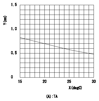
1. Determine the timer advance angle using the graph.
2. Adjust with the screw so that the timer advance angle determined in item 1 is obtained.
X = temperature t (deg C)
Y = timer stroke TA (mm)
(A) = timer stroke
----------
----------
TA=TA=-0.0235t+1.17
----------
----------
TA=TA=-0.0235t+1.17
Information:
Table 1
Features Benefits
All engineering changes and updates included Improved reliability and performance
Worldwide availability through the Cat® Parts Distribution System Customer access regardless of location
Off the shelf reliability Downtime reduced through exchanged product
Same as new Caterpillar warranty Consistent support
Illustration 1 g06211468
(1) Rocker arm with MEUI-C hardware
(2) Rocker arm with MEUI-A hardwareNote: The 192-4151 Button is being replaced with the 258-8721 Button on MEUI-A injector rocker arms. Either button can be used for both types of injectors.
Table 2
MEUI-C Rocker MEUI-A Rocker
258-8721 Button 192-4151 Button
274-4492 Arm Adjustment Screw 196-5069 Arm Adjustment Screw
8L-2777 O-Ring Seal 061-8639 O-Ring Seal
Table 3
Reman Part Number New Part Number Machine Serial Number Prefixes
20R-3319 437-3881 221, 530, 819, 880, 986, 1DL, 1XJ, 24W, 25W, 26W, 27W, 2TW, 2YD, 3F6, 3KR, 3SK, 45P, 4SK, 5TJ, 5TW, 6AB, 6PR, 6YF, 6XJ, 6YZ, 7MZ, 86Z, 87X, 87Z, 9TC, A4G, A9P, AKA, AMA, ANS, APF, ARW, ASW, AWW, AYT, AZW, B1N, BCC, BKX, BLY, BRL, BTW, BTX, BXD, BXY, BYP, CMX, DBB, DBC, DHF, DHJ, DHT, DHX, DJK, DLS, DLW, DN6, DNM, DNR, DNW, DR3, DS3, DS9, DW9, E4S, EDA, EED, EXD, EYG, FCT, FDL, FEN, FKD, GEB, GT7, GXR, H25, H4C, H8M, H9K, HJD, HS2, JCM, JET, JJW, JLK, JMS, JNS, JNW, JRP, JXP, KBC, KCZ, KDH, KDP, KGB, KK2, KK3, KLK, KLS, KNW, KPZ, KSD, KZL, L4F, LFJ, LFK, LFN, LTX, LWY, MB8, MBE, MCY, MDG, MFL, MKP, MWH, MYA, NEL, NNW, P4J, P4L, PAR, PAX, PJA, PT7, RAB, RCD, RCY, RFM, RLB, RM2, RM3, RMA, RME, RWB, SEE, SET, T2F, T4P, T4S, T4Y, T5S, T5W, TFJ, TNM, TWA, TWG, TYE, W1B, W1F, WBT, WSN, WT6, WTW, WTX, WWC, WWD, Z4D, Z4Z, ZAC, ZMX
20R-3322 437-3862 232, 233, 234, 818, 1AB, 1FB, 1NB, 1JB, 2GB, 2KR, 2PS, 2SR, 2XW, 3ND, 47M, 5EW, 5YR, 6BK, 6GZ, 6TB, 6TR, 71W, 7CG, 7KR, 7XM, 85X, 86X, 8PS, 90Z, A7A, A8J, ALP, ANW, AP4, ASX, AT2, AW4, AWF, AWH, AWR, AXB, AXF, AXG, AXM, AYH, AZZ, B1P, B1R, B93, B9K, BBB, BDS, BKF, BNH, BPC, BWX, BZZ, CB2, CEN, CES, CEX, CLD, CLS, CXM, CXR, DBD, DFA, DFJ, DHB, DHD, DHG, DHL, DP4, DPE, DT8, DWJ, DXB, DXE, DXG, DXR, E4R, EAM, EBF, ECM, ECX, ELC, FAT, FH9, FMC, GAY, GER, GLH, GLK, GWC, GXM, H27, HSM, J2M, J8B, JKC, JR8, KEX, KJW, KKJ, KKK, L4D, L4E, L8S, LH9, LTS, LWA, LWX, LWZ, M1M, M3P, M3W, M4E, MB9, MCS, MEM, MEX, MH8, MHG, MLN, MMA, MNZ, MSE, MSF, N64, NFJ, NLK, P1C, P1M, PAP, PAS, PF8, PNM, RCM, RJG, RJS, SBE, SJY, T2E, T4R, TAS, TEC, TLB, TPB, TWZ, W1C, W1E, WAG, WAP, WAW, WTK, XP8, Z4X, Z9K
Table 4
Reman Part Number New Part Number Engine Serial Number Prefixes
20R-3319 437-3881 115, 127, 132, 137, 173, 174, 175, 2A3, 3LW, 5DS, 7CZ, 8AZ, 9NN, 9YP, AL6, AN2, AR2, AR3, ASW, AT4, AZW, B2C, B3G, BEM, BFM, BGA, BXS, C1G, C2T, C4G, C5E, C5L, C6C, CAH, CCB, CE5, CKH, CWJ, DCT, DDS, DGK, DGL, DKE, DSJ, DWB, E1Y, GB3, GBM, GDS, GEN, GES, GRS, GSZ, GTB,