Information injection-pump assembly
ZEXEL
104741-1481
1047411481
ISUZU
8944528252
8944528252

Rating:
Cross reference number
ZEXEL
104741-1481
1047411481
ISUZU
8944528252
8944528252
Zexel num
Bosch num
Firm num
Name
Calibration Data:
Adjustment conditions
Test oil
1404 Test oil ISO4113orSAEJ967d
1404 Test oil ISO4113orSAEJ967d
Test oil temperature
degC
45
45
50
Nozzle
105000-2010
Bosch type code
NP-DN12SD12TT
Nozzle holder
105780-2080
Opening pressure
MPa
14.7
14.7
15.19
Opening pressure
kgf/cm2
150
150
155
Injection pipe
Inside diameter - outside diameter - length (mm) mm 2-6-840
Inside diameter - outside diameter - length (mm) mm 2-6-840
Transfer pump pressure
kPa
20
20
20
Transfer pump pressure
kgf/cm2
0.2
0.2
0.2
Direction of rotation (viewed from drive side)
Left L
Left L
Injection timing adjustment
Pump speed
r/min
1250
1250
1250
Boost pressure
kPa
46.7
45.4
48
Boost pressure
mmHg
350
340
360
Average injection quantity
mm3/st.
49.1
48.6
50.6
Difference in delivery
mm3/st.
4.5
Basic
*
Oil temperature
degC
50
48
52
Remarks
CBS
CBS
Injection timing adjustment_02
Pump speed
r/min
1250
1250
1250
Boost pressure
kPa
93.3
92
94.6
Boost pressure
mmHg
700
690
710
Average injection quantity
mm3/st.
60.9
60.4
61.4
Difference in delivery
mm3/st.
3.5
Basic
*
Oil temperature
degC
50
48
52
Remarks
Full
Full
Injection timing adjustment_03
Pump speed
r/min
600
600
600
Boost pressure
kPa
13.3
12
14.6
Boost pressure
mmHg
100
90
110
Average injection quantity
mm3/st.
36
32
40
Oil temperature
degC
48
46
50
Injection timing adjustment_04
Pump speed
r/min
750
750
750
Boost pressure
kPa
24
22.7
25.3
Boost pressure
mmHg
180
170
190
Average injection quantity
mm3/st.
38.2
38.2
38.2
Oil temperature
degC
50
48
52
Injection timing adjustment_05
Pump speed
r/min
900
900
900
Boost pressure
kPa
46.7
45.4
48
Boost pressure
mmHg
350
340
360
Average injection quantity
mm3/st.
48.2
48.2
48.2
Oil temperature
degC
50
48
52
Injection timing adjustment_06
Pump speed
r/min
1250
1250
1250
Boost pressure
kPa
46.7
45.4
48
Boost pressure
mmHg
350
340
360
Average injection quantity
mm3/st.
49.1
48.1
50.1
Difference in delivery
mm3/st.
4.5
Basic
*
Oil temperature
degC
50
48
52
Injection timing adjustment_07
Pump speed
r/min
1250
1250
1250
Boost pressure
kPa
93.3
92
94.6
Boost pressure
mmHg
700
690
710
Average injection quantity
mm3/st.
60.9
59.9
61.9
Difference in delivery
mm3/st.
3.5
Basic
*
Oil temperature
degC
50
48
52
Injection timing adjustment_08
Pump speed
r/min
1800
1800
1800
Boost pressure
kPa
93.3
92
94.6
Boost pressure
mmHg
700
690
710
Average injection quantity
mm3/st.
58.3
54.8
61.8
Difference in delivery
mm3/st.
5.5
Oil temperature
degC
50
48
52
Injection quantity adjustment
Pump speed
r/min
2300
2300
2300
Boost pressure
kPa
93.3
92
94.6
Boost pressure
mmHg
700
690
710
Average injection quantity
mm3/st.
16.5
13.5
19.5
Difference in delivery
mm3/st.
4.5
Basic
*
Oil temperature
degC
52
50
54
Injection quantity adjustment_02
Pump speed
r/min
2600
2600
2600
Boost pressure
kPa
93.3
92
94.6
Boost pressure
mmHg
700
690
710
Average injection quantity
mm3/st.
5
Oil temperature
degC
55
52
58
Injection quantity adjustment_03
Pump speed
r/min
2300
2300
2300
Boost pressure
kPa
93.3
92
94.6
Boost pressure
mmHg
700
690
710
Average injection quantity
mm3/st.
16.5
13.5
19.5
Difference in delivery
mm3/st.
4.5
Oil temperature
degC
52
50
54
Governor adjustment
Pump speed
r/min
375
375
375
Boost pressure
kPa
0
0
0
Boost pressure
mmHg
0
0
0
Average injection quantity
mm3/st.
7
5
9
Difference in delivery
mm3/st.
2
Basic
*
Oil temperature
degC
48
46
50
Governor adjustment_02
Pump speed
r/min
375
375
375
Boost pressure
kPa
0
0
0
Boost pressure
mmHg
0
0
0
Average injection quantity
mm3/st.
7
5
9
Difference in delivery
mm3/st.
2
Oil temperature
degC
48
46
50
Timer adjustment
Pump speed
r/min
100
100
100
Boost pressure
kPa
0
0
0
Boost pressure
mmHg
0
0
0
Average injection quantity
mm3/st.
80
60
100
Basic
*
Oil temperature
degC
48
46
50
Remarks
IDLE
IDLE
Timer adjustment_02
Pump speed
r/min
100
100
100
Boost pressure
kPa
0
0
0
Boost pressure
mmHg
0
0
0
Average injection quantity
mm3/st.
80
60
100
Oil temperature
degC
48
46
50
Speed control lever angle
Pump speed
r/min
375
375
375
Boost pressure
kPa
0
0
0
Boost pressure
mmHg
0
0
0
Average injection quantity
mm3/st.
0
0
0
Oil temperature
degC
48
46
50
Remarks
Magnet OFF at idling position
Magnet OFF at idling position
0000000901
Pump speed
r/min
1600
1600
1600
Boost pressure
kPa
93.3
92
94.6
Boost pressure
mmHg
700
690
710
Overflow quantity
cm3/min
400
270
530
Oil temperature
degC
50
48
52
Stop lever angle
Pump speed
r/min
1600
1600
1600
Boost pressure
kPa
93.3
92
94.6
Boost pressure
mmHg
700
690
710
Pressure
kPa
490
470
510
Pressure
kgf/cm2
5
4.8
5.2
Basic
*
Oil temperature
degC
50
48
52
Stop lever angle_02
Pump speed
r/min
1050
1050
1050
Boost pressure
kPa
93.3
92
94.6
Boost pressure
mmHg
700
690
710
Pressure
kPa
314
285
343
Pressure
kgf/cm2
3.2
2.9
3.5
Oil temperature
degC
50
48
52
Stop lever angle_03
Pump speed
r/min
1600
1600
1600
Boost pressure
kPa
93.3
92
94.6
Boost pressure
mmHg
700
690
710
Pressure
kPa
490
470
510
Pressure
kgf/cm2
5
4.8
5.2
Oil temperature
degC
50
48
52
Stop lever angle_04
Pump speed
r/min
1800
1800
1800
Boost pressure
kPa
93.3
92
94.6
Boost pressure
mmHg
700
690
710
Pressure
kPa
549
520
578
Pressure
kgf/cm2
5.6
5.3
5.9
Basic
*
Oil temperature
degC
50
48
52
0000001101
Pump speed
r/min
1600
1600
1600
Boost pressure
kPa
93.3
92
94.6
Boost pressure
mmHg
700
690
710
Timer stroke
mm
5
4.8
5.2
Basic
*
Oil temperature
degC
50
48
52
_02
Pump speed
r/min
1050
1050
1050
Boost pressure
kPa
93.3
92
94.6
Boost pressure
mmHg
700
690
710
Timer stroke
mm
0.5
0.1
0.9
Oil temperature
degC
50
48
52
_03
Pump speed
r/min
1600
1600
1600
Boost pressure
kPa
93.3
92
94.6
Boost pressure
mmHg
700
690
710
Timer stroke
mm
5
4.8
5.2
Oil temperature
degC
50
48
52
_04
Pump speed
r/min
1800
1800
1800
Boost pressure
kPa
93.3
92
94.6
Boost pressure
mmHg
700
690
710
Timer stroke
mm
6.2
5.9
6.6
Basic
*
Oil temperature
degC
50
48
52
0000001201
Max. applied voltage
V
8
8
8
Test voltage
V
13
12
14
Timing setting
K dimension
mm
2.8
2.7
2.9
KF dimension
mm
5.5
5.4
5.6
MS dimension
mm
0.9
0.8
1
BCS stroke
mm
4.8
4.6
5
Pre-stroke
mm
0.45
0.43
0.47
Control lever angle alpha
deg.
18
14
22
Control lever angle beta
deg.
37
32
42
Test data Ex:
0000001801 V-FICD ADJUSTMENT
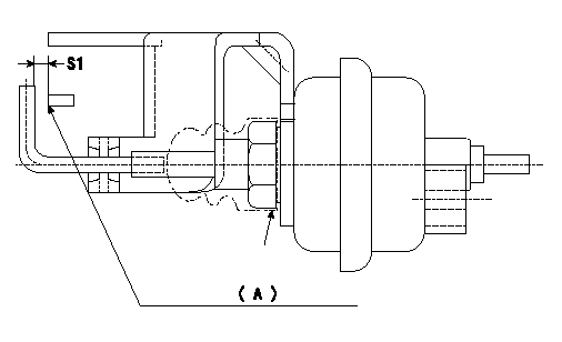
Adjustment of the V-FICD
1. Adjust the actuator rod to obtain S1.
2. Apply negative pressure P1 kPa {P2 mmHg} to the actuator and confirm that it moves through its full stroke.
(A) Control lever (Idling position)
----------
S1=1+1mm P1=-53.3kPa P2=-400mmHg
----------
S1=1+1mm
----------
S1=1+1mm P1=-53.3kPa P2=-400mmHg
----------
S1=1+1mm
Information:
Illustration 13 g02915447
Plugged DOC
The DOC utilizes a “pass-through” technology, which is different from the “wall flow” design of a DPF. When a light is shined through the DOC, a visible light should be able to pass through. Utilize a flashlight to check for a plugged DOC face. Aim the flashlight into the DOC inlet, visible light should be seen through the DOC. A plugged DOC can be caused by high oil consumption, not recommended fuel additives, or wrong engine oil types. Refer to the Operation and Maintenance Manual for recommended fluids to use. If light cannot be seen on the outlet of the DOC, then replace the DOC.CRS Bodies
Illustration 14 g06342815
Combustion Group
(1) Head Group - Combustion
(2) Gasket
(3) Tube
(4) Body Assembly - Exhaust CombustionCRS Combustion Body (4) contains the flame necessary for CRS Regeneration. There are two combustion stages that occur within the CRS Body: the primary and secondary combustion. The primary combustion of air and fuel occur within Tube (3) to create the CRS flame immediately following Head Group (1). The secondary combustion of the CRS flame and exhaust gas from the turbocharger occur within Body Assembly (4).The body assembly is the only salvageable part of the combustion group. The body assembly must be cleaned, inspected, and pressure tested prior to reuse.Cleaning
Start by isolating the CRS body from all other CRS exhaust components. Remove the head group, the mounting studs, the tube, and the two gaskets.The gasket area and the bellows joints are the two areas of the CRS body that must be cleaned thoroughly to make a proper seal.Cleaning the remainder of the CRS body is not required. If cleaning the CRS body is desired, then first perform the visual inspection, vacuum inspection, and welding procedures prior to washing the CRS body. This step is to ensure that the CRS body is salvageable, not cracked, and to keep water from getting trapped behind the heat shield.If washing is preferred, then use soap and water as a cleaning solution. Do not submerge the CRS body to prevent water from becoming trapped between the heat shield and the CRS body. A cylinder washing brush, a wire brush with handle, and a greenScotch Brite pads are all acceptable cleaning equipment. Removal of all diesel particulates is not required for inspection.
Do not use any combustible solvents to clean the CRS body.
Visual Inspection
A visual inspection of the CRS body must be completed, special equipment or crack detecting solution is not required. Visually inspect the exterior of the CRS body. Small cracks and/or punctures found on the stainless steel heat shield is normal and should be expected. Inspect the bellows sealing joints and the CRS head mating surface for visual damage.Light surface rust is typically not a problem unless rust is found on a bellows joint or the CRS gasket mating surface. Light rust in these two areas must be removed using a Scotch Brite pad.Serviceability
All bolts, studs, and clamps are not reusable and must be replaced with new components.Any thread damage in the mounting