Information injection-pump assembly
ZEXEL
104741-1470
1047411470
ISUZU
8944528150
8944528150
Rating:
Cross reference number
ZEXEL
104741-1470
1047411470
ISUZU
8944528150
8944528150
Zexel num
Bosch num
Firm num
Name
Calibration Data:
Adjustment conditions
Test oil
1404 Test oil ISO4113orSAEJ967d
1404 Test oil ISO4113orSAEJ967d
Test oil temperature
degC
45
45
50
Nozzle
105000-2010
Bosch type code
NP-DN12SD12TT
Nozzle holder
105780-2080
Opening pressure
MPa
14.7
14.7
15.19
Opening pressure
kgf/cm2
150
150
155
Injection pipe
Inside diameter - outside diameter - length (mm) mm 2-6-840
Inside diameter - outside diameter - length (mm) mm 2-6-840
Transfer pump pressure
kPa
20
20
20
Transfer pump pressure
kgf/cm2
0.2
0.2
0.2
Direction of rotation (viewed from drive side)
Left L
Left L
Injection timing adjustment
Pump speed
r/min
1150
1150
1150
Average injection quantity
mm3/st.
47.5
47
48
Difference in delivery
mm3/st.
3.5
Basic
*
Oil temperature
degC
50
48
52
Injection timing adjustment_02
Pump speed
r/min
500
500
500
Average injection quantity
mm3/st.
40.6
37.1
44.1
Oil temperature
degC
48
46
50
Injection timing adjustment_03
Pump speed
r/min
750
750
750
Average injection quantity
mm3/st.
36.5
34.5
38.5
Oil temperature
degC
50
48
52
Injection timing adjustment_04
Pump speed
r/min
1150
1150
1150
Average injection quantity
mm3/st.
41.7
40.7
42.7
Difference in delivery
mm3/st.
3.5
Basic
*
Oil temperature
degC
50
48
52
Injection timing adjustment_05
Pump speed
r/min
1500
1500
1500
Average injection quantity
mm3/st.
43.2
43.2
43.2
Oil temperature
degC
50
48
52
Injection timing adjustment_06
Pump speed
r/min
1900
1900
1900
Average injection quantity
mm3/st.
42.3
42.3
42.3
Oil temperature
degC
50
48
52
Injection timing adjustment_07
Pump speed
r/min
2000
2000
2000
Average injection quantity
mm3/st.
39.7
36.7
42.7
Difference in delivery
mm3/st.
5.5
Oil temperature
degC
50
48
52
Injection quantity adjustment
Pump speed
r/min
2300
2300
2300
Average injection quantity
mm3/st.
10.9
7.9
13.9
Difference in delivery
mm3/st.
3.5
Basic
*
Oil temperature
degC
52
50
54
Injection quantity adjustment_02
Pump speed
r/min
2500
2500
2500
Average injection quantity
mm3/st.
6
Oil temperature
degC
55
52
58
Injection quantity adjustment_03
Pump speed
r/min
2300
2300
2300
Average injection quantity
mm3/st.
24.1
21.1
27.1
Difference in delivery
mm3/st.
3.5
Oil temperature
degC
52
50
54
Governor adjustment
Pump speed
r/min
375
375
375
Average injection quantity
mm3/st.
6
4
8
Difference in delivery
mm3/st.
2
Basic
*
Oil temperature
degC
48
46
50
Governor adjustment_02
Pump speed
r/min
375
375
375
Average injection quantity
mm3/st.
6
4
8
Difference in delivery
mm3/st.
2
Oil temperature
degC
48
46
50
Timer adjustment
Pump speed
r/min
100
100
100
Average injection quantity
mm3/st.
75
75
115
Basic
*
Oil temperature
degC
48
46
50
Timer adjustment_02
Pump speed
r/min
100
100
100
Average injection quantity
mm3/st.
80
60
100
Oil temperature
degC
48
46
50
Speed control lever angle
Pump speed
r/min
375
375
375
Average injection quantity
mm3/st.
0
0
0
Oil temperature
degC
48
46
50
Remarks
Magnet OFF at idling position
Magnet OFF at idling position
0000000901
Pump speed
r/min
1600
1600
1600
Oil temperature
degC
50
48
52
Remarks
MEASURE
MEASURE
Stop lever angle
Pump speed
r/min
1600
1600
1600
Pressure with S/T OFF
kPa
490
470
510
Pressure with S/T OFF
kgf/cm2
5
4.8
5.2
Basic
*
Oil temperature
degC
50
48
52
Stop lever angle_02
Pump speed
r/min
1600
1600
1600
Pressure
kPa
490
470
510
Pressure
kgf/cm2
5
4.8
5.2
Basic
*
Oil temperature
degC
50
48
52
Stop lever angle_03
Pump speed
r/min
2000
2000
2000
Pressure
kPa
608
579
637
Pressure
kgf/cm2
6.2
5.9
6.5
Oil temperature
degC
50
48
52
0000001101
Pump speed
r/min
1600
1600
1600
Timer stroke with S/T OFF
mm
4.8
4.6
5
Basic
*
Oil temperature
degC
50
48
52
_02
Pump speed
r/min
1020
1020
1020
Timer stroke
mm
0.5
0.5
0.5
Oil temperature
degC
50
48
52
_03
Pump speed
r/min
1600
1600
1600
Timer stroke
mm
4.8
4.6
5
Basic
*
Oil temperature
degC
50
48
52
_04
Pump speed
r/min
2000
2000
2000
Timer stroke
mm
7.8
7.5
8.2
Oil temperature
degC
50
48
52
0000001201
Max. applied voltage
V
8
8
8
Test voltage
V
13
12
14
0000001501
Pump speed
r/min
1150
1150
1150
Height
m
2000
2000
2000
Atmospheric pressure difference
kPa
-21.9
-21.9
-21.9
Atmospheric pressure difference
mmHg
-164
-164
-164
Average injection quantity
mm3/st.
39
39
39
Decrease qty
mm3/st.
8.5
7
10
Decrease rate
%
18
18
18
Basic
*
Oil temperature
degC
50
48
52
_02
Pump speed
r/min
1150
1150
1150
Height
m
0
0
0
Atmospheric pressure difference
kPa
0
0
0
Atmospheric pressure difference
mmHg
0
0
0
Decrease qty
mm3/st.
0
0
0
Decrease rate
%
0
0
0
Oil temperature
degC
50
48
52
_03
Pump speed
r/min
1150
1150
1150
Height
m
500
500
500
Atmospheric pressure difference
kPa
-5.9
-9.2
-2.6
Atmospheric pressure difference
mmHg
-44
-69
-19
Oil temperature
degC
50
48
52
Remarks
Point of inflection
Point of inflection
_04
Pump speed
r/min
1150
1150
1150
Height
m
2000
2000
2000
Atmospheric pressure difference
kPa
-21.9
-21.9
-21.9
Atmospheric pressure difference
mmHg
-164
-164
-164
Decrease qty
mm3/st.
-7.5
-7.5
-7.5
Decrease rate
%
-18
-21
-15
Oil temperature
degC
50
48
52
Timing setting
K dimension
mm
2.8
2.7
2.9
KF dimension
mm
5.5
5.4
5.6
MS dimension
mm
1
0.9
1.1
Pre-stroke
mm
0.45
0.43
0.47
Control lever angle alpha
deg.
18
14
22
Control lever angle beta
deg.
37
32
42
Test data Ex:
0000001801 MICROSWITCH ADJUSTMENT
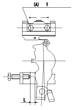
Microswitch adjustment
1.Fix the control lever so that the distance between the control lever and the idling stopper bolt is L (control lever position: a).
2. In the above condition, adjust the installation position of the microswitch so that so that it turns OFF.
Must change from ON to OFF at L1. [Lever angle b (from idle).]
(A): microswitch fixing bolt
----------
L=6.0mm L1=5.6~6.4mm a=14deg b=13~15deg
----------
T=2~3N-m(0.2~0.3kgf-m) L=6.0mm
----------
L=6.0mm L1=5.6~6.4mm a=14deg b=13~15deg
----------
T=2~3N-m(0.2~0.3kgf-m) L=6.0mm
0000001901 V-FICD ADJUSTMENT
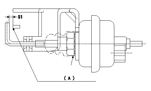
Adjustment of the V-FICD
1. Adjust the actuator rod to obtain S1.
2. Apply negative pressure P1 kPa {P2 mmHg} to the actuator and confirm that it moves through its full stroke.
(A) Control lever (Idling position)
----------
S1=1+1mm P1=-53.3kPa P2=-400mmHg
----------
S1=1+1mm
----------
S1=1+1mm P1=-53.3kPa P2=-400mmHg
----------
S1=1+1mm
Information:
Install the pump cover onto the pump housing. Tighten the four middle bolts. Then, tighten the end bolts in a crisscross pattern. Tighten the bolts to a torque of 10.2 N m (90 lb in).Note: Make sure that the gasket is in place between the housing and the cover.
Repeat Step 1 and Step 2 in order to confirm the electrical connection for the pump coil was not damaged during the removal of the pump cover.
Install the oil inlet line adapter, inlet line, and harness connector to the pump.Note: After the HEUI pump is replaced or reassembled, the engine must be cranked for an extended length of time to fill the pump with oil.Note: Clear any diagnostic or event codes that activated during the initial start-up.
If the engine would not start before inspecting for debris and no debris was found in the HEUI pump, return to Step D in the diagnostic flow chart.If the engine would start before inspecting for debris and no debris was found in the HEUI pump, return to Step L in the diagnostic flow chart.If the pump is to be replaced, complete the checklist form in Special Instruction, REHS5031 that is provided with the service replacement part and insert the completed form back into the box containing the part that is being returned. Proceed to the section of this instruction titled "Oil Rail Cleaning Procedure" for the correct engine size that is being serviced.Oil Rail Cleaning Procedure For the C7 Engine
Illustration 12 g02702636
C7 Cylinder Head
Illustration 13 g02708256
The oil and fuel passages are the same for both the C7 and C9.
(6) Oil Rail for a HEUI fuel system
(7) Oil passage to injector bore
(8) Fuel passage
(9) Injector bore Note: Contain any oil and cleaner that will flow from the cylinder and the lines during the following process. Properly dispose of the oil and contaminated cleaner when work is complete.
Remove fuel injectors. Refer to Disassembly and Assembly for specific machine.
Install six plugs 9U-7080 Tapered Cap/Plug into the lower injector bores. The plugs will prevent oil, cleaners, and debris from entering the cylinders.
Remove the plugs from the front and rear of the cylinder head main oil gallery
Remove the pressure sensor from the cylinder head. Protect the sensor.
Clean out the two rail drain holes by removing their plugs and using the brake cleaner and long squirting straw to flush these passages to the oil rail.
Using the solvent gun with and without the