Information injection-pump assembly
BOSCH
9 460 613 493
9460613493
ZEXEL
104741-1443
1047411443
ISUZU
8944336253
8944336253

Rating:
Cross reference number
BOSCH
9 460 613 493
9460613493
ZEXEL
104741-1443
1047411443
ISUZU
8944336253
8944336253
Zexel num
Bosch num
Firm num
Name
104741-1443
9 460 613 493
8944336253 ISUZU
INJECTION-PUMP ASSEMBLY
4JD1 K
4JD1 K
Calibration Data:
Adjustment conditions
Test oil
1404 Test oil ISO4113orSAEJ967d
1404 Test oil ISO4113orSAEJ967d
Test oil temperature
degC
45
45
50
Nozzle
105000-2010
Bosch type code
NP-DN12SD12TT
Nozzle holder
105780-2080
Opening pressure
MPa
14.7
14.7
15.19
Opening pressure
kgf/cm2
150
150
155
Injection pipe
Inside diameter - outside diameter - length (mm) mm 2-6-840
Inside diameter - outside diameter - length (mm) mm 2-6-840
Transfer pump pressure
kPa
20
20
20
Transfer pump pressure
kgf/cm2
0.2
0.2
0.2
Direction of rotation (viewed from drive side)
Left L
Left L
Timer measuring device installation position
Low pressure side LOW PRESSURE SIDE
Low pressure side LOW PRESSURE SIDE
Injection timing adjustment
Pump speed
r/min
1100
1100
1100
Average injection quantity
mm3/st.
38.3
37.8
38.8
Difference in delivery
mm3/st.
3.5
Basic
*
Injection timing adjustment_02
Pump speed
r/min
1420
1420
1420
Average injection quantity
mm3/st.
13.9
10.4
17.4
Injection timing adjustment_03
Pump speed
r/min
1300
1300
1300
Average injection quantity
mm3/st.
35.1
32.6
37.6
Injection timing adjustment_04
Pump speed
r/min
1100
1100
1100
Average injection quantity
mm3/st.
38.3
37.3
39.3
Injection timing adjustment_05
Pump speed
r/min
800
800
800
Average injection quantity
mm3/st.
41.1
38.1
44.1
Injection timing adjustment_06
Pump speed
r/min
600
600
600
Average injection quantity
mm3/st.
39.8
36.3
43.3
Injection quantity adjustment
Pump speed
r/min
1420
1420
1420
Average injection quantity
mm3/st.
13.9
10.9
16.9
Difference in delivery
mm3/st.
4.5
Basic
*
Injection quantity adjustment_02
Pump speed
r/min
1450
1450
1450
Average injection quantity
mm3/st.
6
Governor adjustment
Pump speed
r/min
425
425
425
Average injection quantity
mm3/st.
9.3
7.3
11.3
Difference in delivery
mm3/st.
2
Basic
*
Governor adjustment_02
Pump speed
r/min
500
500
500
Average injection quantity
mm3/st.
3
Governor adjustment_03
Pump speed
r/min
425
425
425
Average injection quantity
mm3/st.
9.3
7.3
11.3
Governor adjustment_04
Pump speed
r/min
350
350
350
Average injection quantity
mm3/st.
26.4
21.4
31.4
Timer adjustment
Pump speed
r/min
100
100
100
Average injection quantity
mm3/st.
70
60
80
Basic
*
Speed control lever angle
Pump speed
r/min
425
425
425
Average injection quantity
mm3/st.
0
0
0
Remarks
Magnet OFF
Magnet OFF
0000000901
Pump speed
r/min
800
800
800
Overflow quantity
cm3/min
300
168
432
Stop lever angle
Pump speed
r/min
800
800
800
Pressure
kPa
264.5
245
284
Pressure
kgf/cm2
2.7
2.5
2.9
Basic
*
Stop lever angle_02
Pump speed
r/min
800
800
800
Pressure
kPa
264.5
245
284
Pressure
kgf/cm2
2.7
2.5
2.9
Stop lever angle_03
Pump speed
r/min
1200
1200
1200
Pressure
kPa
411.5
382
441
Pressure
kgf/cm2
4.2
3.9
4.5
0000001101
Pump speed
r/min
800
800
800
Timer stroke
mm
1.8
1.6
2
Basic
*
_02
Pump speed
r/min
600
600
600
Timer stroke
mm
0.5
0.1
0.9
_03
Pump speed
r/min
800
800
800
Timer stroke
mm
1.8
1.5
2.1
_04
Pump speed
r/min
1200
1200
1200
Timer stroke
mm
4.4
4
4.8
0000001201
Max. applied voltage
V
8
8
8
Test voltage
V
13
12
14
Timing setting
K dimension
mm
2.8
2.7
2.9
KF dimension
mm
5
4.9
5.1
MS dimension
mm
1.9
1.8
2
Pre-stroke
mm
0.15
0.13
0.17
Control lever angle alpha
deg.
20
16
24
Control lever angle beta
deg.
37
32
42
Test data Ex:
0000001801 STARTING I/Q ADJUSTMENT
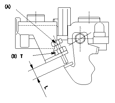
Starting injection quantity adjustment
Adjust the adjusting bolt A so that the starting injection quantity adjustment is within the standards.
Fix using nut (B).
----------
----------
L=7.4~11.1mm T=6~9N-m(0.6~0.9kgf-m)
----------
----------
L=7.4~11.1mm T=6~9N-m(0.6~0.9kgf-m)
Information:
Do not operate or work on this product unless you have read and understood the instruction and warnings in the relevant Operation and Maintenance Manuals and relevant service literature. Failure to follow the instructions or heed the warnings could result in injury or death. Proper care is your responsibility.
The following changes are adaptable to machines within the listed serial numbers and are effective with all machines after the listed serial numbers.
Illustration 1 g06325715
View of Air lines group on 966M, 972M, 966M XE, and 972M XE machines
(1) 415-8220 Hose
(2) 8T-6703 Hose Clamp
(3) 211-8073 Protection Cap
Illustration 2 g06325708
View of Air lines group on 980M and 982M machines
(1) 365-0045 Hose
(2) 8T-6703 Hose Clamp
(3) 211-8073 Protection Cap
Table 1
Required Parts
Item Qty New Part Number Part Name Former Part Number
1 1 415-8220 (1) Hose 415-8220
365-0045 (2) 365-0045
2 2 8T-6703 Hose Clamp (3) 296-5807
3 2 211-8073 Protection Cap 7X-1443
(1) For 966M, 972M, 966M XE, and 972M XE machines
(2) For 980M and 982M machines
(3) Torque for the hose clamps is 11 2 N m (97 18 lb in).If the CRS hose is found damaged on the above listed machines, replace the hose with same part number. Use hose clamp (2) and protection cap (3) to secure the new hose.The new hose clamp (2) replaces the existing 296-5807 Clamp. The new protection cap (3) replaces the existing 7X-1443 Protector on machines listed above.Torque the hose clamps (2) to 11 2 N m (97 18 lb in).
Have questions with 104741-1443?
Group cross 104741-1443 ZEXEL
Isuzu
104741-1443
9 460 613 493
8944336253
INJECTION-PUMP ASSEMBLY
4JD1
4JD1