Information injection-pump assembly
ZEXEL
104741-1422
1047411422
ISUZU
8944528372
8944528372

Rating:
Components :
| 0. | INJECTION-PUMP ASSEMBLY | 104741-1422 |
| 1. | _ | |
| 2. | FUEL INJECTION PUMP | |
| 3. | NUMBER PLATE | |
| 4. | _ | |
| 5. | CAPSULE | |
| 6. | ADJUSTING DEVICE | |
| 7. | NOZZLE AND HOLDER ASSY | 105118-4404 |
| 8. | Nozzle and Holder | |
| 9. | Open Pre:MPa(Kqf/cm2) | 18.1(185) |
| 10. | NOZZLE-HOLDER | 105048-3220 |
| 11. | NOZZLE | 105017-0550 |
Include in #2:
104741-1422
as INJECTION-PUMP ASSEMBLY
Cross reference number
ZEXEL
104741-1422
1047411422
ISUZU
8944528372
8944528372
Zexel num
Bosch num
Firm num
Name
Calibration Data:
Adjustment conditions
Test oil
1404 Test oil ISO4113orSAEJ967d
1404 Test oil ISO4113orSAEJ967d
Test oil temperature
degC
45
45
50
Nozzle
105000-2010
Bosch type code
NP-DN12SD12TT
Nozzle holder
105780-2080
Opening pressure
MPa
14.7
14.7
15.19
Opening pressure
kgf/cm2
150
150
155
Injection pipe
Inside diameter - outside diameter - length (mm) mm 2-6-840
Inside diameter - outside diameter - length (mm) mm 2-6-840
Transfer pump pressure
kPa
20
20
20
Transfer pump pressure
kgf/cm2
0.2
0.2
0.2
Direction of rotation (viewed from drive side)
Left L
Left L
Injection timing adjustment
Pump speed
r/min
1250
1250
1250
Boost pressure
kPa
46.65
45.3
48
Boost pressure
mmHg
350
340
360
Average injection quantity
mm3/st.
49.4
48.9
49.9
Difference in delivery
mm3/st.
4.5
Basic
*
Remarks
CBS
CBS
Injection timing adjustment_02
Pump speed
r/min
1250
1250
1250
Boost pressure
kPa
80
78.7
81.3
Boost pressure
mmHg
600
590
610
Average injection quantity
mm3/st.
61.3
60.8
61.8
Difference in delivery
mm3/st.
3.5
Basic
*
Remarks
Full
Full
Injection timing adjustment_03
Pump speed
r/min
2300
2300
2300
Boost pressure
kPa
80
78.7
81.3
Boost pressure
mmHg
600
590
610
Average injection quantity
mm3/st.
16.6
13.1
20.1
Injection timing adjustment_04
Pump speed
r/min
1800
1800
1800
Boost pressure
kPa
80
78.7
81.3
Boost pressure
mmHg
600
590
610
Average injection quantity
mm3/st.
58.6
55.1
62.1
Injection timing adjustment_05
Pump speed
r/min
1250
1250
1250
Boost pressure
kPa
80
78.7
81.3
Boost pressure
mmHg
600
590
610
Average injection quantity
mm3/st.
61.3
60.3
62.3
Remarks
Full
Full
Injection timing adjustment_06
Pump speed
r/min
1250
1250
1250
Boost pressure
kPa
46.65
45.3
48
Boost pressure
mmHg
350
340
360
Average injection quantity
mm3/st.
49.4
48.4
50.4
Remarks
CBS
CBS
Injection timing adjustment_07
Pump speed
r/min
900
900
900
Boost pressure
kPa
46.65
45.3
48
Boost pressure
mmHg
350
340
360
Average injection quantity
mm3/st.
49.5
46
53
Injection timing adjustment_08
Pump speed
r/min
750
750
750
Boost pressure
kPa
24
22.7
25.3
Boost pressure
mmHg
180
170
190
Average injection quantity
mm3/st.
39.4
35.9
42.9
Injection timing adjustment_09
Pump speed
r/min
600
600
600
Boost pressure
kPa
13.35
12
14.7
Boost pressure
mmHg
100
90
110
Average injection quantity
mm3/st.
36
32
40
Injection quantity adjustment
Pump speed
r/min
2300
2300
2300
Boost pressure
kPa
80
78.7
81.3
Boost pressure
mmHg
600
590
610
Average injection quantity
mm3/st.
16.6
13.6
19.6
Difference in delivery
mm3/st.
4.5
Basic
*
Injection quantity adjustment_02
Pump speed
r/min
2600
2600
2600
Boost pressure
kPa
80
78.7
81.3
Boost pressure
mmHg
600
590
610
Average injection quantity
mm3/st.
5
Governor adjustment
Pump speed
r/min
375
375
375
Boost pressure
kPa
0
0
0
Boost pressure
mmHg
0
0
0
Average injection quantity
mm3/st.
7
5
9
Difference in delivery
mm3/st.
2
Basic
*
Governor adjustment_02
Pump speed
r/min
375
375
375
Boost pressure
kPa
0
0
0
Boost pressure
mmHg
0
0
0
Average injection quantity
mm3/st.
7
5
9
Governor adjustment_03
Pump speed
r/min
500
500
500
Boost pressure
kPa
0
0
0
Boost pressure
mmHg
0
0
0
Average injection quantity
mm3/st.
3
Timer adjustment
Pump speed
r/min
100
100
100
Boost pressure
kPa
0
0
0
Boost pressure
mmHg
0
0
0
Average injection quantity
mm3/st.
80
60
100
Basic
*
Speed control lever angle
Pump speed
r/min
375
375
375
Boost pressure
kPa
0
0
0
Boost pressure
mmHg
0
0
0
Average injection quantity
mm3/st.
0
0
0
Remarks
Magnet OFF
Magnet OFF
0000000901
Pump speed
r/min
1600
1600
1600
Boost pressure
kPa
0
0
0
Boost pressure
mmHg
0
0
0
Overflow quantity with S/T OFF
cm3/min
561
432
690
Remarks
MEASURE
MEASURE
Stop lever angle
Pump speed
r/min
1600
1600
1600
Boost pressure
kPa
80
78.7
81.3
Boost pressure
mmHg
600
590
610
Pressure with S/T OFF
kPa
490.5
471
510
Pressure with S/T OFF
kgf/cm2
5
4.8
5.2
Basic
*
Stop lever angle_02
Pump speed
r/min
1600
1600
1600
Boost pressure
kPa
80
78.7
81.3
Boost pressure
mmHg
600
590
610
Pressure with S/T OFF
kPa
490.5
471
510
Pressure with S/T OFF
kgf/cm2
5
4.8
5.2
Stop lever angle_03
Pump speed
r/min
1800
1800
1800
Boost pressure
kPa
80
78.7
81.3
Boost pressure
mmHg
600
590
610
Pressure with S/T OFF
kPa
539.5
510
569
Pressure with S/T OFF
kgf/cm2
5.5
5.2
5.8
0000001101
Pump speed
r/min
1600
1600
1600
Boost pressure
kPa
80
78.7
81.3
Boost pressure
mmHg
600
590
610
Timer stroke with S/T OFF
mm
5
4.8
5.2
Basic
*
_02
Pump speed
r/min
520
520
520
Boost pressure
kPa
80
78.7
81.3
Boost pressure
mmHg
600
590
610
Timer stroke with S/T ON
mm
0.5
0.5
_03
Pump speed
r/min
1600
1600
1600
Boost pressure
kPa
80
78.7
81.3
Boost pressure
mmHg
600
590
610
Timer stroke with S/T OFF
mm
5
4.7
5.3
_04
Pump speed
r/min
1800
1800
1800
Boost pressure
kPa
80
78.7
81.3
Boost pressure
mmHg
600
590
610
Timer stroke with S/T OFF
mm
6.2
5.8
6.6
0000001201
Max. applied voltage
V
8
8
8
Test voltage
V
13
12
14
Timing setting
K dimension
mm
2.8
2.7
2.9
KF dimension
mm
5.5
5.4
5.6
MS dimension
mm
0.9
0.8
1
BCS stroke
mm
4.8
4.7
4.9
Pre-stroke
mm
0.45
0.43
0.47
Control lever angle alpha
deg.
18
14
22
Control lever angle beta
deg.
37
32
42
Test data Ex:
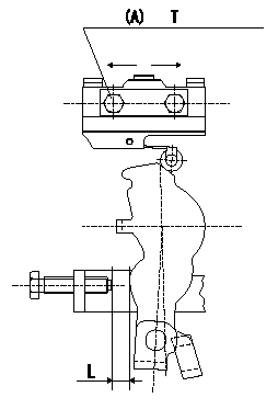
0000001801 MICROSWITCH ADJUSTMENT

Microswitch adjustment
1.Fix the control lever so that the distance between the control lever and the idling stopper bolt is L (control lever position: a).
2. In the above condition, adjust the installation position of the microswitch so that so that it turns OFF.
Must change from ON to OFF at L1. [Lever angle b (from idle).]
(A): microswitch fixing bolt
----------
L=6.0mm L1=5.6~6.4mm a=14deg b=13~15deg
----------
T=2~3N-m(0.2~0.3kgf-m) L=6.0mm
----------
L=6.0mm L1=5.6~6.4mm a=14deg b=13~15deg
----------
T=2~3N-m(0.2~0.3kgf-m) L=6.0mm
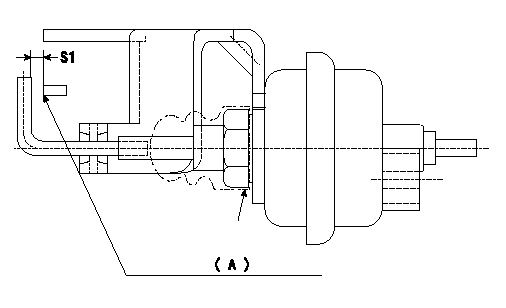
0000001901 V-FICD ADJUSTMENT

Adjustment of the V-FICD
1. Adjust the actuator rod to obtain S1.
2. Apply negative pressure P1 kPa {P2 mmHg} to the actuator and confirm that it moves through its full stroke.
(A) Control lever (Idling position)
----------
S1=1+1mm P1=-53.3kPa P2=-400mmHg
----------
S1=1+1mm
----------
S1=1+1mm P1=-53.3kPa P2=-400mmHg
----------
S1=1+1mm
Information:
Introduction
Do not perform any procedure in this Special Instruction until you read this information and you understand this information.This Special Instruction is intended to provide instructions on installing O-Ring seals on the injector sleeves.Required Parts
Table 1
Required Parts
Part Number Part Name Quantity
227-1200 Injector Sleeve 6
310-7255 O-Ring Seal 6
310-7257 O-Ring Seal 6 Required Tools
Table 2
Required Tools
Part Number Part Name Quantity
221-9777 Sleeve Installer 1
4C-5552 Large Bore Brush 1
4C-9507 Retaining Compound 1 Cleaning the Injector Sleeves and Installing O-Ring Seal
Note: Thoroughly clean the injector sleeves with the 4C-5552 Large Bore Brush .Note: Thoroughly clean the bore in the cylinder head for the injector sleeves with the 4C-5552 Large Bore Brush .Note: Do not apply any lubricant to the O-ring seals.
Illustration 1 g01379557
(1) 310-7255 O-Ring Seal (2) 310-7257 O-Ring Seal (3) 227-1200 Injector Sleeve
Install the upper O-Ring (1) on the injector sleeve (3) .Note: The upper O-Ring is dark blue.
Install the lower O-Ring (2) on the injector sleeve (3) .Note: The lower O-Ring (2) is turquoise.
Position the injector sleeve on the 221-9777 Sleeve Installer .
Apply a thin coat of 4C-9507 Retaining Compound around the outer circumference of area (A). Ensure that the retaining compound does not make contact with the O-Ring seal at any time.
Position the injector sleeve (3) in the cylinder head by using the 221-9777 Sleeve Installer .
Slowly push the injector sleeve into the cylinder head by gently tapping with a hammer.Note: Allow the 4C-9507 Retaining Compound to cure for two hours at 21 °C (70 °F) before filling the engine with coolant. Longer curing time is required for lower temperatures.
Install the unit injectors. Refer to Disassembly and Assembly, "Unit Injector-Install" to install the unit injectors.