Information injection-pump assembly
ZEXEL
104741-1421
1047411421
Rating:
Cross reference number
ZEXEL
104741-1421
1047411421
Zexel num
Bosch num
Firm num
Name
Calibration Data:
Adjustment conditions
Test oil
1404 Test oil ISO4113orSAEJ967d
1404 Test oil ISO4113orSAEJ967d
Test oil temperature
degC
45
45
50
Nozzle
105000-2010
Bosch type code
NP-DN12SD12TT
Nozzle holder
105780-2080
Opening pressure
MPa
14.7
14.7
15.19
Opening pressure
kgf/cm2
150
150
155
Injection pipe
Inside diameter - outside diameter - length (mm) mm 2-6-840
Inside diameter - outside diameter - length (mm) mm 2-6-840
Transfer pump pressure
kPa
20
20
20
Transfer pump pressure
kgf/cm2
0.2
0.2
0.2
Direction of rotation (viewed from drive side)
Left L
Left L
(Solenoid timer adjustment condition)
OFF
Injection timing adjustment
Pump speed
r/min
900
900
900
Boost pressure
kPa
44
42.7
45.3
Boost pressure
mmHg
330
320
340
Average injection quantity
mm3/st.
49.6
49.1
50.1
Difference in delivery
mm3/st.
4.5
Basic
*
Oil temperature
degC
50
48
52
Remarks
CBS
CBS
Injection timing adjustment_02
Pump speed
r/min
1150
1150
1150
Boost pressure
kPa
74.6
73.3
75.9
Boost pressure
mmHg
560
550
570
Average injection quantity
mm3/st.
62.6
62.1
63.1
Difference in delivery
mm3/st.
3.5
Basic
*
Oil temperature
degC
50
48
52
Remarks
Full
Full
Injection timing adjustment_03
Pump speed
r/min
500
500
500
Boost pressure
kPa
0
0
0
Boost pressure
mmHg
0
0
0
Average injection quantity
mm3/st.
36.6
33.1
40.1
Oil temperature
degC
48
46
50
Injection timing adjustment_04
Pump speed
r/min
750
750
750
Boost pressure
kPa
26.7
25.4
28
Boost pressure
mmHg
200
190
210
Average injection quantity
mm3/st.
41
41
41
Oil temperature
degC
50
48
52
Injection timing adjustment_05
Pump speed
r/min
900
900
900
Boost pressure
kPa
44
42.7
45.3
Boost pressure
mmHg
330
320
340
Average injection quantity
mm3/st.
49.6
48.6
50.6
Basic
*
Oil temperature
degC
50
48
52
Injection timing adjustment_06
Pump speed
r/min
1150
1150
1150
Boost pressure
kPa
74.6
73.3
75.9
Boost pressure
mmHg
560
550
570
Average injection quantity
mm3/st.
62.6
61.6
63.6
Difference in delivery
mm3/st.
3.5
Basic
*
Oil temperature
degC
50
48
52
Injection timing adjustment_07
Pump speed
r/min
1900
1900
1900
Boost pressure
kPa
80
78.7
81.3
Boost pressure
mmHg
600
590
610
Average injection quantity
mm3/st.
53.9
50.4
57.4
Difference in delivery
mm3/st.
5.5
Oil temperature
degC
50
48
52
Injection quantity adjustment
Pump speed
r/min
2300
2300
2300
Boost pressure
kPa
80
78.7
81.3
Boost pressure
mmHg
600
590
610
Average injection quantity
mm3/st.
19.9
16.9
22.9
Difference in delivery
mm3/st.
4.5
Basic
*
Oil temperature
degC
52
50
54
Injection quantity adjustment_02
Pump speed
r/min
2400
2400
2400
Boost pressure
kPa
80
78.7
81.3
Boost pressure
mmHg
600
590
610
Average injection quantity
mm3/st.
8
Oil temperature
degC
52
50
54
Injection quantity adjustment_03
Pump speed
r/min
2300
2300
2300
Boost pressure
kPa
80
78.7
81.3
Boost pressure
mmHg
600
590
610
Average injection quantity
mm3/st.
19.9
16.9
22.9
Difference in delivery
mm3/st.
4.5
Oil temperature
degC
52
50
54
Governor adjustment
Pump speed
r/min
375
375
375
Boost pressure
kPa
0
0
0
Boost pressure
mmHg
0
0
0
Average injection quantity
mm3/st.
8
6
10
Difference in delivery
mm3/st.
2
Basic
*
Oil temperature
degC
48
46
50
Governor adjustment_02
Pump speed
r/min
375
375
375
Boost pressure
kPa
0
0
0
Boost pressure
mmHg
0
0
0
Average injection quantity
mm3/st.
8
6
10
Difference in delivery
mm3/st.
2
Oil temperature
degC
48
46
50
Timer adjustment
Pump speed
r/min
100
100
100
Boost pressure
kPa
0
0
0
Boost pressure
mmHg
0
0
0
Average injection quantity
mm3/st.
75
75
115
Basic
*
Oil temperature
degC
48
46
50
Remarks
Full
Full
Timer adjustment_02
Pump speed
r/min
100
100
100
Boost pressure
kPa
0
0
0
Boost pressure
mmHg
0
0
0
Average injection quantity
mm3/st.
95
75
115
Oil temperature
degC
48
46
50
Speed control lever angle
Pump speed
r/min
375
375
375
Boost pressure
kPa
0
0
0
Boost pressure
mmHg
0
0
0
Average injection quantity
mm3/st.
0
0
0
Oil temperature
degC
48
46
50
Remarks
Magnet OFF at idling position
Magnet OFF at idling position
Speed control lever angle_02
Pump speed
r/min
375
375
375
Boost pressure
kPa
0
0
0
Boost pressure
mmHg
0
0
0
Average injection quantity
mm3/st.
0
0
0
Oil temperature
degC
48
46
50
Remarks
Magnet OFF at full-load position
Magnet OFF at full-load position
0000000901
Pump speed
r/min
1450
1450
1450
Boost pressure
kPa
0
0
0
Boost pressure
mmHg
0
0
0
Oil temperature
degC
50
48
52
Remarks
MEASURE
MEASURE
Stop lever angle
Pump speed
r/min
1450
1450
1450
Boost pressure
kPa
0
0
0
Boost pressure
mmHg
0
0
0
Pressure with S/T OFF
kPa
461
441
481
Pressure with S/T OFF
kgf/cm2
4.7
4.5
4.9
Basic
*
Oil temperature
degC
50
48
52
Stop lever angle_02
Pump speed
r/min
1450
1450
1450
Boost pressure
kPa
0
0
0
Boost pressure
mmHg
0
0
0
Pressure with S/T OFF
kPa
461
432
490
Pressure with S/T OFF
kgf/cm2
4.7
4.5
4.9
Basic
*
Oil temperature
degC
50
48
52
Stop lever angle_03
Pump speed
r/min
2000
2000
2000
Boost pressure
kPa
0
0
0
Boost pressure
mmHg
0
0
0
Pressure with S/T OFF
kPa
608
579
637
Pressure with S/T OFF
kgf/cm2
6.2
5.9
6.5
Oil temperature
degC
50
48
52
0000001101
Pump speed
r/min
1450
1450
1450
Boost pressure
kPa
0
0
0
Boost pressure
mmHg
0
0
0
Timer stroke with S/T OFF
mm
4.1
3.9
4.3
Basic
*
Oil temperature
degC
50
48
52
_02
Pump speed
r/min
770
670
870
Boost pressure
kPa
0
0
0
Boost pressure
mmHg
0
0
0
Timer stroke with S/T ON
mm
0.5
0.5
0.5
Oil temperature
degC
50
48
52
_03
Pump speed
r/min
1020
970
1070
Boost pressure
kPa
0
0
0
Boost pressure
mmHg
0
0
0
Timer stroke with S/T OFF
mm
0.5
0.5
0.5
Oil temperature
degC
50
48
52
_04
Pump speed
r/min
1450
1450
1450
Boost pressure
kPa
0
0
0
Boost pressure
mmHg
0
0
0
Timer stroke with S/T OFF
mm
4.1
3.9
4.3
Basic
*
Oil temperature
degC
50
48
52
_05
Pump speed
r/min
2000
2000
2000
Boost pressure
kPa
0
0
0
Boost pressure
mmHg
0
0
0
Timer stroke with S/T OFF
mm
7.8
7.5
8.2
Oil temperature
degC
50
48
52
0000001201
Max. applied voltage
V
8
8
8
Test voltage
V
13
12
14
Timing setting
K dimension
mm
2.8
2.7
2.9
KF dimension
mm
5.5
5.4
5.6
MS dimension
mm
1
0.9
1.1
BCS stroke
mm
5
4.9
5.1
Pre-stroke
mm
0.45
0.43
0.47
Control lever angle alpha
deg.
18
14
22
Control lever angle beta
deg.
37
32
42
Test data Ex:
0000001801 MICROSWITCH ADJUSTMENT
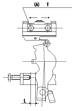
Microswitch adjustment
1. Insert a shim L mm (control lever position: a) between the control lever and the idling stopper bolt.
2. Move the microswitch in the direction of the arrow so that it turns ON.
3. Move the microswitch again in the direction of the arrow and tighten the microswitch fixing bolt where it turns OFF.
Must change from ON to OFF at L1. [Lever angle b (from idle).]
(A): microswitch fixing bolt
----------
L=6.0mm L1=5.6~6.4mm a=14deg b=13~15deg
----------
T=2~3N-m(0.2~0.3kgf-m) L=6.0mm
----------
L=6.0mm L1=5.6~6.4mm a=14deg b=13~15deg
----------
T=2~3N-m(0.2~0.3kgf-m) L=6.0mm
0000001901 V-FICD ADJUSTMENT
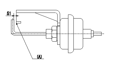
Adjustment of the V-FICD
1. Adjust the actuator rod to obtain S1.
2. Apply negative pressure P1 to the actuator and confirm the full stroke.
(A) Control lever (Idling position)
----------
S1=1+1mm P1=-53.3kPa(-400mmHg)
----------
S1=1+1mm
----------
S1=1+1mm P1=-53.3kPa(-400mmHg)
----------
S1=1+1mm
Information:
These recommendations are subject to change without notice. Consult your local Cat dealer for the most up to date recommendations.
Diesel engines may burn a wide variety of fuels. These fuels are divided into two general groups. The two groups are called the preferred fuels and the permissible fuels.The preferred fuels provide maximum engine service life and performance. The preferred fuels are distillate fuels. These fuels are commonly called diesel fuel, furnace oil, gas oil, or kerosene. These fuels must meet the “Cat Specification for Distillate Diesel Fuel for Off-Highway Diesel Engines” found in this Special Publication, "Distillate Diesel Fuel" article.The permissible fuels are some crude oils, some blends of crude oil with distillate fuel, and some marine diesel fuel. These fuels are not suitable for use in all engine applications. The acceptability of these fuels for use is determined on a case by case basis. A complete fuel analysis is required. Consult your Cat dealer for further information. Biodiesel fuel is permissible for use in Cat engines. Follow all the recommendations and guidelines given in this Special Publication, "Biodiesel" article.Note: Except for some biodiesel, permissible fuels are not acceptable for use in on-highway applications.
Use of permissible fuels can result in higher maintenance costs and reduced engine service life.
Note: Use of fuels that do not meet at least the minimum performance recommendations and/or requirements may lead to lower compartment performance and/or compartment failure. Problems/failures that are caused by using fuels that do not meet the minimum recommended and/or required performance level are not Cat factory defects and therefore are NOT covered by the Cat warranty. The fuel supplier and customer are responsible.