Information injection-pump assembly
ZEXEL
104741-1410
1047411410
ISUZU
8944528310
8944528310

Rating:
Cross reference number
ZEXEL
104741-1410
1047411410
ISUZU
8944528310
8944528310
Zexel num
Bosch num
Firm num
Name
Calibration Data:
Adjustment conditions
Test oil
1404 Test oil ISO4113orSAEJ967d
1404 Test oil ISO4113orSAEJ967d
Test oil temperature
degC
45
45
50
Nozzle
105000-2010
Bosch type code
NP-DN12SD12TT
Nozzle holder
105780-2080
Opening pressure
MPa
14.7
14.7
15.19
Opening pressure
kgf/cm2
150
150
155
Injection pipe
Inside diameter - outside diameter - length (mm) mm 2-6-840
Inside diameter - outside diameter - length (mm) mm 2-6-840
Transfer pump pressure
kPa
20
20
20
Transfer pump pressure
kgf/cm2
0.2
0.2
0.2
Direction of rotation (viewed from drive side)
Left L
Left L
(Solenoid timer adjustment condition)
OFF OFF
OFF OFF
Injection timing adjustment
Pump speed
r/min
900
900
900
Boost pressure
kPa
45.3
44
46.6
Boost pressure
mmHg
340
330
350
Average injection quantity
mm3/st.
49.5
49
50
Difference in delivery
mm3/st.
4.5
Basic
*
Oil temperature
degC
50
48
52
Remarks
CBS
CBS
Injection timing adjustment_02
Pump speed
r/min
1150
1150
1150
Boost pressure
kPa
80
78.7
81.3
Boost pressure
mmHg
600
590
610
Average injection quantity
mm3/st.
62.2
61.7
62.7
Difference in delivery
mm3/st.
3.5
Basic
*
Oil temperature
degC
50
48
52
Remarks
Full
Full
Injection timing adjustment_03
Pump speed
r/min
500
500
500
Boost pressure
kPa
0
0
0
Boost pressure
mmHg
0
0
0
Average injection quantity
mm3/st.
42.9
39.4
46.4
Oil temperature
degC
48
46
50
Injection timing adjustment_04
Pump speed
r/min
750
750
750
Boost pressure
kPa
27.3
26
28.6
Boost pressure
mmHg
205
195
215
Average injection quantity
mm3/st.
42.3
42.3
42.3
Oil temperature
degC
50
48
52
Injection timing adjustment_05
Pump speed
r/min
900
900
900
Boost pressure
kPa
45.3
44
46.6
Boost pressure
mmHg
340
330
350
Average injection quantity
mm3/st.
49.5
48.5
50.5
Basic
*
Oil temperature
degC
50
48
52
Injection timing adjustment_06
Pump speed
r/min
1150
1150
1150
Boost pressure
kPa
80
78.7
81.3
Boost pressure
mmHg
600
590
610
Average injection quantity
mm3/st.
62.2
61.2
63.2
Difference in delivery
mm3/st.
3.5
Basic
*
Oil temperature
degC
50
48
52
Injection timing adjustment_07
Pump speed
r/min
1900
1900
1900
Boost pressure
kPa
80
78.7
81.3
Boost pressure
mmHg
600
590
610
Average injection quantity
mm3/st.
53.2
49.2
57.2
Difference in delivery
mm3/st.
5.5
Oil temperature
degC
50
48
52
Injection quantity adjustment
Pump speed
r/min
2300
2300
2300
Boost pressure
kPa
80
78.7
81.3
Boost pressure
mmHg
600
590
610
Average injection quantity
mm3/st.
27.5
24.5
30.5
Difference in delivery
mm3/st.
4.5
Basic
*
Oil temperature
degC
52
50
54
Injection quantity adjustment_02
Pump speed
r/min
2400
2400
2400
Boost pressure
kPa
80
78.7
81.3
Boost pressure
mmHg
600
590
610
Average injection quantity
mm3/st.
13
Oil temperature
degC
55
52
58
Injection quantity adjustment_03
Pump speed
r/min
2300
2300
2300
Boost pressure
kPa
80
78.7
81.3
Boost pressure
mmHg
600
590
610
Average injection quantity
mm3/st.
27.5
24.5
30.5
Difference in delivery
mm3/st.
4.5
Oil temperature
degC
52
50
54
Governor adjustment
Pump speed
r/min
375
375
375
Boost pressure
kPa
0
0
0
Boost pressure
mmHg
0
0
0
Average injection quantity
mm3/st.
9
7
11
Difference in delivery
mm3/st.
2
Basic
*
Oil temperature
degC
48
46
50
Governor adjustment_02
Pump speed
r/min
375
375
375
Boost pressure
kPa
0
0
0
Boost pressure
mmHg
0
0
0
Average injection quantity
mm3/st.
9
7
11
Difference in delivery
mm3/st.
2
Oil temperature
degC
48
46
50
Timer adjustment
Pump speed
r/min
100
100
100
Boost pressure
kPa
0
0
0
Boost pressure
mmHg
0
0
0
Average injection quantity
mm3/st.
95
75
115
Basic
*
Oil temperature
degC
48
46
50
Remarks
Full
Full
Timer adjustment_02
Pump speed
r/min
100
100
100
Boost pressure
kPa
0
0
0
Boost pressure
mmHg
0
0
0
Average injection quantity
mm3/st.
75
75
115
Oil temperature
degC
48
46
50
Speed control lever angle
Pump speed
r/min
375
375
375
Boost pressure
kPa
0
0
0
Boost pressure
mmHg
0
0
0
Average injection quantity
mm3/st.
0
0
0
Oil temperature
degC
48
46
50
Remarks
Magnet OFF at idling position
Magnet OFF at idling position
0000000901
Pump speed
r/min
1600
1600
1600
Boost pressure
kPa
0
0
0
Boost pressure
mmHg
0
0
0
Oil temperature
degC
50
48
52
Remarks
MEASURE
MEASURE
Stop lever angle
Pump speed
r/min
1600
1600
1600
Boost pressure
kPa
0
0
0
Boost pressure
mmHg
0
0
0
Pressure with S/T OFF
kPa
490
470
510
Pressure with S/T OFF
kgf/cm2
5
4.8
5.2
Basic
*
Oil temperature
degC
50
48
52
Stop lever angle_02
Pump speed
r/min
1600
1600
1600
Boost pressure
kPa
0
0
0
Boost pressure
mmHg
0
0
0
Pressure with S/T OFF
kPa
490
470
510
Pressure with S/T OFF
kgf/cm2
5
4.8
5.2
Basic
*
Oil temperature
degC
50
48
52
Stop lever angle_03
Pump speed
r/min
2000
2000
2000
Boost pressure
kPa
0
0
0
Boost pressure
mmHg
0
0
0
Pressure with S/T OFF
kPa
608
579
637
Pressure with S/T OFF
kgf/cm2
6.2
5.9
6.5
Oil temperature
degC
50
48
52
0000001101
Pump speed
r/min
1600
1600
1600
Boost pressure
kPa
0
0
0
Boost pressure
mmHg
0
0
0
Timer stroke with S/T OFF
mm
4.8
4.6
5
Basic
*
Oil temperature
degC
50
48
52
_02
Pump speed
r/min
1020
1020
1020
Boost pressure
kPa
0
0
0
Boost pressure
mmHg
0
0
0
Timer stroke with S/T OFF
mm
0.5
0.5
0.5
Oil temperature
degC
50
48
52
_03
Pump speed
r/min
1600
1600
1600
Boost pressure
kPa
0
0
0
Boost pressure
mmHg
0
0
0
Timer stroke with S/T OFF
mm
4.8
4.6
5
Basic
*
Oil temperature
degC
50
48
52
_04
Pump speed
r/min
2000
2000
2000
Boost pressure
kPa
0
0
0
Boost pressure
mmHg
0
0
0
Timer stroke with S/T OFF
mm
7.8
7.5
8.2
Oil temperature
degC
50
48
52
0000001201
Max. applied voltage
V
8
8
8
Test voltage
V
13
12
14
Timing setting
K dimension
mm
2.8
2.7
2.9
KF dimension
mm
5.5
5.4
5.6
MS dimension
mm
1
0.9
1.1
BCS stroke
mm
3.2
3
3.4
Pre-stroke
mm
0.45
0.43
0.47
Control lever angle alpha
deg.
18
14
22
Control lever angle beta
deg.
37
32
42
Test data Ex:
0000001801 MICROSWITCH ADJUSTMENT
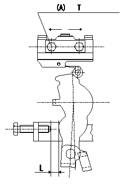
Microswitch adjustment
1.Fix the control lever so that the distance between the control lever and the idling stopper bolt is L (control lever position: a).
2. In the above condition, adjust the installation position of the microswitch so that so that it turns OFF.
(A) = microswitch fixing bolt
----------
L=6.0+-0.2mm a=14deg
----------
T=2~3N-m(0.2~0.3kgf-m) L=6.0+-0.2mm
----------
L=6.0+-0.2mm a=14deg
----------
T=2~3N-m(0.2~0.3kgf-m) L=6.0+-0.2mm
0000001901 V-FICD ADJUSTMENT
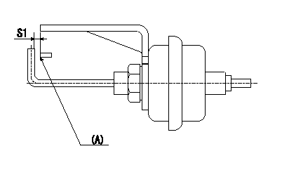
Adjustment of the V-FICD
1. Adjust the actuator rod to obtain S1.
2. Apply negative pressure P1 to the actuator and confirm the full stroke.
(A) Control lever (Idling position)
----------
S1=1+1mm P1=-53.3kPa(-400mmHg)
----------
S1=1+1mm
----------
S1=1+1mm P1=-53.3kPa(-400mmHg)
----------
S1=1+1mm
Information:
Events
The events are used in order to record a problem that is detected by the control system. Events are also used to document adverse engine operation. Events will be communicated to the service tool via the CDL. An event indicates that the control system has detected an engine problem. An event does not indicate an electronic problem. For example, the high exhaust temperature event is disabled if a problem with the temperature sensor is detected. (Events can be configured to be triggered on a diagnostic.)An event is identified by a numerical code. The EID (Event Identifier) identifies an engine problem or a problem with the machine. The service tool is used to display the EID. The service tool adds descriptive text for each EID in order to avoid mistakes in interpreting the codes.Logged Events
When an event is activated, information about the event is logged into permanent memory for the Electronic Control Module. The CDL can then request this information from the ECM. The CDL will display the following information for each logged event. Up to twenty five different events can be logged. Events are not automatically erased.
EID
FMI
Description of the event
Number of occurrences
The first time of occurrence
The last time of occurrenceEvents may be cleared from the memory of the ECM in order to use the CDL. Logged events can be configured so that a factory password is required to clear the event. Table 1 references the Event Codes that can be seen in order to use the Diesel Particulate Filter Monitor System.
Table 1
EID Description Security Level
194 Warning for the High Exhaust Temperature 1
194 Critical Warning for the High Exhaust Temperature 2
1049 Warning for the Pressure Inlet for the High Particulate Trap 1
1049 Critical Warning for the Pressure Inlet for the High Particulate Trap 2