Information injection-pump assembly
ZEXEL
104741-1393
1047411393
ISUZU
8944751621
8944751621
Rating:
Cross reference number
ZEXEL
104741-1393
1047411393
ISUZU
8944751621
8944751621
Zexel num
Bosch num
Firm num
Name
Calibration Data:
Adjustment conditions
Test oil
1404 Test oil ISO4113orSAEJ967d
1404 Test oil ISO4113orSAEJ967d
Test oil temperature
degC
45
45
50
Nozzle
105000-2010
Bosch type code
NP-DN12SD12TT
Nozzle holder
105780-2080
Opening pressure
MPa
14.7
14.7
15.19
Opening pressure
kgf/cm2
150
150
155
Injection pipe
Inside diameter - outside diameter - length (mm) mm 2-6-840
Inside diameter - outside diameter - length (mm) mm 2-6-840
Transfer pump pressure
kPa
20
20
20
Transfer pump pressure
kgf/cm2
0.2
0.2
0.2
Direction of rotation (viewed from drive side)
Right R
Right R
(Solenoid timer adjustment condition)
OFF
Injection timing adjustment
Pump speed
r/min
900
900
900
Boost pressure
kPa
44
42.7
45.3
Boost pressure
mmHg
330
320
340
Average injection quantity
mm3/st.
54.3
53.8
54.8
Difference in delivery
mm3/st.
4.5
Basic
*
Oil temperature
degC
50
48
52
Remarks
CBS
CBS
Injection timing adjustment_02
Pump speed
r/min
1250
1250
1250
Boost pressure
kPa
80
78.7
81.3
Boost pressure
mmHg
600
590
610
Average injection quantity
mm3/st.
62.4
61.9
62.9
Difference in delivery
mm3/st.
3.5
Basic
*
Oil temperature
degC
50
48
52
Remarks
Full
Full
Injection timing adjustment_03
Pump speed
r/min
500
500
500
Boost pressure
kPa
0
0
0
Boost pressure
mmHg
0
0
0
Average injection quantity
mm3/st.
37.5
34
41
Difference in delivery
mm3/st.
5.5
Oil temperature
degC
48
46
50
Injection timing adjustment_04
Pump speed
r/min
750
750
750
Boost pressure
kPa
26.7
25.4
28
Boost pressure
mmHg
200
190
210
Average injection quantity
mm3/st.
45.7
45.7
45.7
Oil temperature
degC
50
48
52
Injection timing adjustment_05
Pump speed
r/min
900
900
900
Boost pressure
kPa
44
42.7
45.3
Boost pressure
mmHg
330
320
340
Average injection quantity
mm3/st.
54.3
53.3
55.3
Difference in delivery
mm3/st.
4.5
Basic
*
Oil temperature
degC
50
48
52
Injection timing adjustment_06
Pump speed
r/min
1250
1250
1250
Boost pressure
kPa
80
78.7
81.3
Boost pressure
mmHg
600
590
610
Average injection quantity
mm3/st.
62.4
61.4
63.4
Difference in delivery
mm3/st.
3.5
Basic
*
Oil temperature
degC
50
48
52
Injection timing adjustment_07
Pump speed
r/min
1900
1900
1900
Boost pressure
kPa
80
78.7
81.3
Boost pressure
mmHg
600
590
610
Average injection quantity
mm3/st.
57.8
52.3
63.3
Difference in delivery
mm3/st.
5.5
Oil temperature
degC
50
48
52
Injection quantity adjustment
Pump speed
r/min
2300
2300
2300
Boost pressure
kPa
80
78.7
81.3
Boost pressure
mmHg
600
590
610
Average injection quantity
mm3/st.
19.7
16.7
22.7
Difference in delivery
mm3/st.
4.5
Basic
*
Oil temperature
degC
52
50
54
Injection quantity adjustment_02
Pump speed
r/min
2400
2400
2400
Boost pressure
kPa
80
78.7
81.3
Boost pressure
mmHg
600
590
610
Average injection quantity
mm3/st.
11
Oil temperature
degC
52
50
54
Injection quantity adjustment_03
Pump speed
r/min
2300
2300
2300
Boost pressure
kPa
80
78.7
81.3
Boost pressure
mmHg
600
590
610
Average injection quantity
mm3/st.
19.7
16.7
22.7
Difference in delivery
mm3/st.
4.5
Oil temperature
degC
52
50
54
Governor adjustment
Pump speed
r/min
385
385
385
Boost pressure
kPa
0
0
0
Boost pressure
mmHg
0
0
0
Average injection quantity
mm3/st.
6
4
8
Difference in delivery
mm3/st.
2
Basic
*
Oil temperature
degC
48
46
50
Governor adjustment_02
Pump speed
r/min
385
385
385
Boost pressure
kPa
0
0
0
Boost pressure
mmHg
0
0
0
Average injection quantity
mm3/st.
6
4
8
Difference in delivery
mm3/st.
2
Oil temperature
degC
48
46
50
Timer adjustment
Pump speed
r/min
100
100
100
Boost pressure
kPa
0
0
0
Boost pressure
mmHg
0
0
0
Average injection quantity
mm3/st.
80
60
100
Basic
*
Oil temperature
degC
48
46
50
Timer adjustment_02
Pump speed
r/min
100
100
100
Boost pressure
kPa
0
0
0
Boost pressure
mmHg
0
0
0
Average injection quantity
mm3/st.
80
60
100
Oil temperature
degC
48
46
50
Speed control lever angle
Pump speed
r/min
385
385
385
Boost pressure
kPa
0
0
0
Boost pressure
mmHg
0
0
0
Average injection quantity
mm3/st.
0
0
0
Oil temperature
degC
48
46
50
Remarks
Magnet OFF at idling position
Magnet OFF at idling position
0000000901
Pump speed
r/min
1700
1700
1700
Boost pressure
kPa
80
78.7
81.3
Boost pressure
mmHg
600
590
610
Oil temperature
degC
50
48
52
Remarks
MEASURE
MEASURE
Stop lever angle
Pump speed
r/min
1700
1700
1700
Boost pressure
kPa
80
78.7
81.3
Boost pressure
mmHg
600
590
610
Pressure with S/T OFF
kPa
530
510
550
Pressure with S/T OFF
kgf/cm2
5.4
5.2
5.6
Basic
*
Oil temperature
degC
50
48
52
Stop lever angle_02
Pump speed
r/min
1450
1450
1450
Boost pressure
kPa
80
78.7
81.3
Boost pressure
mmHg
600
590
610
Pressure with S/T OFF
kPa
441
412
470
Pressure with S/T OFF
kgf/cm2
4.5
4.2
4.8
Oil temperature
degC
50
48
52
Stop lever angle_03
Pump speed
r/min
1700
1700
1700
Boost pressure
kPa
80
78.7
81.3
Boost pressure
mmHg
600
590
610
Pressure with S/T OFF
kPa
530
510
550
Pressure with S/T OFF
kgf/cm2
5.4
5.2
5.6
Basic
*
Oil temperature
degC
50
48
52
Stop lever angle_04
Pump speed
r/min
2000
2000
2000
Boost pressure
kPa
80
78.7
81.3
Boost pressure
mmHg
600
590
610
Pressure with S/T OFF
kPa
628
599
657
Pressure with S/T OFF
kgf/cm2
6.4
6.1
6.7
Oil temperature
degC
50
48
52
0000001101
Pump speed
r/min
1700
1700
1700
Boost pressure
kPa
80
78.7
81.3
Boost pressure
mmHg
600
590
610
Timer stroke with S/T OFF
mm
5
4.8
5.2
Basic
*
Oil temperature
degC
50
48
52
_02
Pump speed
r/min
550
550
550
Boost pressure
kPa
80
78.7
81.3
Boost pressure
mmHg
600
590
610
Timer stroke with S/T ON
mm
0.5
0.5
Oil temperature
degC
50
48
52
_03
Pump speed
r/min
1450
1450
1450
Boost pressure
kPa
80
78.7
81.3
Boost pressure
mmHg
600
590
610
Timer stroke with S/T OFF
mm
1.2
0.8
1.6
Oil temperature
degC
50
48
52
_04
Pump speed
r/min
1700
1700
1700
Boost pressure
kPa
80
78.7
81.3
Boost pressure
mmHg
600
590
610
Timer stroke with S/T OFF
mm
5
4.8
5.2
Basic
*
Oil temperature
degC
50
48
52
_05
Pump speed
r/min
2000
2000
2000
Boost pressure
kPa
80
78.7
81.3
Boost pressure
mmHg
600
590
610
Timer stroke with S/T OFF
mm
8.6
8.3
9
Oil temperature
degC
50
48
52
0000001201
Max. applied voltage
V
8
8
8
Test voltage
V
13
12
14
Timing setting
K dimension
mm
2.8
2.7
2.9
KF dimension
mm
5.5
5.4
5.6
MS dimension
mm
0.9
0.8
1
BCS stroke
mm
4.5
4.3
4.7
Pre-stroke
mm
0.45
0.43
0.47
Control lever angle alpha
deg.
18
14
22
Control lever angle beta
deg.
37
32
42
Test data Ex:
0000001801 MICROSWITCH ADJUSTMENT
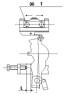
Microswitch adjustment
1. Insert a shim L mm (control lever position: a) between the control lever and the idling stopper bolt.
2. Move the microswitch in the direction of the arrow so that it turns ON.
3. Move the microswitch again in the direction of the arrow and tighten the microswitch fixing bolt where it turns OFF.
Must change from ON to OFF at L1. [Lever angle b (from idle).]
(A): microswitch fixing bolt
----------
L=6.0mm L1=5.6~6.4mm a=14deg b=13~15deg
----------
T=2~3N-m(0.2~0.3kgf-m) L=6.0mm
----------
L=6.0mm L1=5.6~6.4mm a=14deg b=13~15deg
----------
T=2~3N-m(0.2~0.3kgf-m) L=6.0mm
0000001901 V-FICD ADJUSTMENT
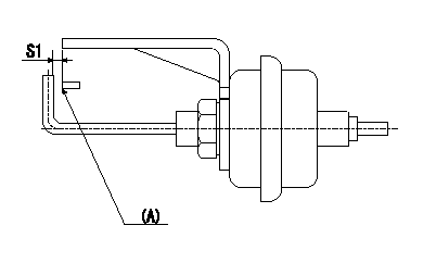
Adjustment of the V-FICD
1. Adjust the actuator rod to obtain S1.
2. Apply negative pressure P1 to the actuator and confirm the full stroke.
(A) Control lever (Idling position)
----------
S1=1+1mm P1=-53.3kPa(-400mmHg)
----------
S1=1+1mm
----------
S1=1+1mm P1=-53.3kPa(-400mmHg)
----------
S1=1+1mm
Information:
The Caterpillar Electronic Technician (ET)
Illustration 1 g00777826
The Caterpillar Electronic Technician (ET) is a software program that is used to access data. The service technician can use the Caterpillar Electronic Technician in order to perform maintenance work on the machine. Some of the options that are available with the Caterpillar Electronic Technician are listed below:
View Diagnostic codes. See Troubleshooting, "Using the Caterpillar Electronic Technician to Determine Diagnostic Codes".
View the status of parameters.
Clear active diagnostic codes and clear logged diagnostic codes
Perform calibration of machine systems.
Program the ECM (Flash). This is done with the "WINflash" program. See Testing and Adjusting, "Electronic Control Module (ECM) - Flash Program".
Print reports.The following list contains some of the diagnostic functions and programming functions that are performed by the service tools.
The failures of the ECM system are displayed.
The status of most of the inputs and the outputs are displayed.
The settings for the ECM are displayed.
Display the status of the input and output parameters in real time.
Display the clock hour of the internal diagnostic clock.
The number of occurrences and the clock hour of the first occurrence and the last occurrence is displayed for each logged diagnostic code.
The definition for each logged diagnostic code and each event is displayed.
Load new FLASH software.See Troubleshooting, "Diagnostic Code List" for the list of diagnostic codes for the ECM.See Troubleshooting, "Using the Caterpillar Electronic Technician to Determine Diagnostic Codes". Diagnostic information is accessed with the following drop down menus:
Active diagnostic codes
Logged diagnostic codesSensor Diagnostics
The following tables show the conditions that the diagnostic codes are set for each sensor. If any of the diagnostic codes are active, the System Problem for the LED will be turned on. During the Debounce time, the affected parameter will remain at the last good value. After the Debounce time, the affected parameter will be set to the default value. Refer to Table 1.
Table 1
Sensor Sample Period (mS) Too Low Too High Defaults
Inlet Pressure (gauge) Code Condition Debounce Code Condition Debounce NA
1 81-4 Input < 0.5 VDC 5 sec on
5 sec off 81-3 Input greater than 4.5 VDC 5 sec on
5 sec off NA
Exhaust Temperature 1 535-4 Input < 1.5 VDC 5 sec on
5 sec off 535-3 Input greater than 4.0 VDC 5 sec on
5 sec off NA Temperature Sensor
Table 2 refers to the properties of the temperature sensor.
Table 2
Function Part Number Measure Range Output Accuracy Power Supply Sensor Mounting Mating
Exhaust Temperature 280-3921
50 °C (122 °F)to
850 °C (1562 °F) N/A
500° 5°C (932° 9°F) to
850° 5°C (1562° 9°F) 5V (+/- 0.5) Thread Size: M14 X 1.5
Probe Length:
70 mm (2.7559 inch) from flange to tip 230-5008 Connector Plug As Pressure Sensor
Table 3
Function PN Max Pressure Measure Burst Pressure Power