Information injection-pump assembly
ZEXEL
104741-1382
1047411382
ISUZU
8944751610
8944751610
Rating:
Cross reference number
ZEXEL
104741-1382
1047411382
ISUZU
8944751610
8944751610
Zexel num
Bosch num
Firm num
Name
Calibration Data:
Adjustment conditions
Test oil
1404 Test oil ISO4113orSAEJ967d
1404 Test oil ISO4113orSAEJ967d
Test oil temperature
degC
45
45
50
Nozzle
105000-2010
Bosch type code
NP-DN12SD12TT
Nozzle holder
105780-2080
Opening pressure
MPa
14.7
14.7
15.19
Opening pressure
kgf/cm2
150
150
155
Injection pipe
Inside diameter - outside diameter - length (mm) mm 2-6-840
Inside diameter - outside diameter - length (mm) mm 2-6-840
Transfer pump pressure
kPa
20
20
20
Transfer pump pressure
kgf/cm2
0.2
0.2
0.2
Direction of rotation (viewed from drive side)
Right R
Right R
Injection timing adjustment
Pump speed
r/min
900
900
900
Boost pressure
kPa
44
42.7
45.3
Boost pressure
mmHg
330
320
340
Average injection quantity
mm3/st.
59.7
59.2
60.2
Difference in delivery
mm3/st.
4.5
Basic
*
Oil temperature
degC
50
48
52
Remarks
CBS
CBS
Injection timing adjustment_02
Pump speed
r/min
1150
1150
1150
Boost pressure
kPa
75.3
74
76.6
Boost pressure
mmHg
565
555
575
Average injection quantity
mm3/st.
68.3
67.8
68.8
Difference in delivery
mm3/st.
3.5
Basic
*
Oil temperature
degC
50
48
52
Remarks
Full
Full
Injection timing adjustment_03
Pump speed
r/min
500
500
500
Boost pressure
kPa
0
0
0
Boost pressure
mmHg
0
0
0
Average injection quantity
mm3/st.
37
33.5
40.5
Oil temperature
degC
48
46
50
Injection timing adjustment_04
Pump speed
r/min
750
750
750
Boost pressure
kPa
26.7
25.4
28
Boost pressure
mmHg
200
190
210
Average injection quantity
mm3/st.
49.6
49.6
49.6
Oil temperature
degC
50
48
52
Injection timing adjustment_05
Pump speed
r/min
900
900
900
Boost pressure
kPa
44
42.7
45.3
Boost pressure
mmHg
330
320
340
Average injection quantity
mm3/st.
59.7
58.7
60.7
Basic
*
Oil temperature
degC
50
48
52
Injection timing adjustment_06
Pump speed
r/min
1150
1150
1150
Boost pressure
kPa
75.3
74
76.6
Boost pressure
mmHg
565
555
575
Average injection quantity
mm3/st.
68.3
67.3
69.3
Difference in delivery
mm3/st.
3.5
Basic
*
Oil temperature
degC
50
48
52
Injection timing adjustment_07
Pump speed
r/min
1900
1900
1900
Boost pressure
kPa
80
78.7
81.3
Boost pressure
mmHg
600
590
610
Average injection quantity
mm3/st.
60.9
55.4
66.4
Difference in delivery
mm3/st.
5.5
Oil temperature
degC
50
48
52
Injection quantity adjustment
Pump speed
r/min
2300
2300
2300
Boost pressure
kPa
80
78.7
81.3
Boost pressure
mmHg
600
590
610
Average injection quantity
mm3/st.
22.9
19.9
25.9
Difference in delivery
mm3/st.
4.5
Basic
*
Oil temperature
degC
52
50
54
Injection quantity adjustment_02
Pump speed
r/min
2400
2400
2400
Boost pressure
kPa
80
78.7
81.3
Boost pressure
mmHg
600
590
610
Average injection quantity
mm3/st.
8
Oil temperature
degC
52
50
54
Injection quantity adjustment_03
Pump speed
r/min
2300
2300
2300
Boost pressure
kPa
80
78.7
81.3
Boost pressure
mmHg
600
590
610
Average injection quantity
mm3/st.
22.9
19.9
25.9
Difference in delivery
mm3/st.
4.5
Oil temperature
degC
52
50
54
Governor adjustment
Pump speed
r/min
385
385
385
Boost pressure
kPa
0
0
0
Boost pressure
mmHg
0
0
0
Average injection quantity
mm3/st.
6
4
8
Difference in delivery
mm3/st.
2
Basic
*
Oil temperature
degC
48
46
50
Governor adjustment_02
Pump speed
r/min
385
385
385
Boost pressure
kPa
0
0
0
Boost pressure
mmHg
0
0
0
Average injection quantity
mm3/st.
6
4
8
Difference in delivery
mm3/st.
2
Oil temperature
degC
48
46
50
Timer adjustment
Pump speed
r/min
100
100
100
Boost pressure
kPa
0
0
0
Boost pressure
mmHg
0
0
0
Average injection quantity
mm3/st.
75
75
115
Basic
*
Oil temperature
degC
48
46
50
Remarks
Full
Full
Timer adjustment_02
Pump speed
r/min
100
100
100
Boost pressure
kPa
0
0
0
Boost pressure
mmHg
0
0
0
Average injection quantity
mm3/st.
92.5
70
115
Oil temperature
degC
48
46
50
Speed control lever angle
Pump speed
r/min
385
385
385
Boost pressure
kPa
0
0
0
Boost pressure
mmHg
0
0
0
Average injection quantity
mm3/st.
0
0
0
Oil temperature
degC
48
46
50
Remarks
Magnet OFF at idling position
Magnet OFF at idling position
0000000901
Pump speed
r/min
1450
1450
1450
Boost pressure
kPa
0
0
0
Boost pressure
mmHg
0
0
0
Oil temperature
degC
50
48
52
Remarks
MEASURE
MEASURE
Stop lever angle
Pump speed
r/min
1450
1450
1450
Boost pressure
kPa
0
0
0
Boost pressure
mmHg
0
0
0
Pressure with S/T OFF
kPa
471
451
491
Pressure with S/T OFF
kgf/cm2
4.8
4.6
5
Basic
*
Oil temperature
degC
50
48
52
Stop lever angle_02
Pump speed
r/min
1450
1450
1450
Boost pressure
kPa
0
0
0
Boost pressure
mmHg
0
0
0
Pressure with S/T OFF
kPa
471
451
491
Pressure with S/T OFF
kgf/cm2
4.8
4.6
5
Basic
*
Oil temperature
degC
50
48
52
Stop lever angle_03
Pump speed
r/min
2000
2000
2000
Boost pressure
kPa
0
0
0
Boost pressure
mmHg
0
0
0
Pressure with S/T OFF
kPa
647
608
686
Pressure with S/T OFF
kgf/cm2
6.6
6.2
7
Oil temperature
degC
50
48
52
0000001101
Pump speed
r/min
1450
1450
1450
Boost pressure
kPa
0
0
0
Boost pressure
mmHg
0
0
0
Timer stroke with S/T OFF
mm
3
2.8
3.2
Basic
*
Oil temperature
degC
50
48
52
_02
Pump speed
r/min
750
750
750
Boost pressure
kPa
0
0
0
Boost pressure
mmHg
0
0
0
Timer stroke with S/T ON
mm
0.5
0.5
0.5
Oil temperature
degC
50
48
52
_03
Pump speed
r/min
1300
1300
1300
Boost pressure
kPa
0
0
0
Boost pressure
mmHg
0
0
0
Timer stroke with S/T OFF
mm
0.5
0.5
0.5
Oil temperature
degC
50
48
52
_04
Pump speed
r/min
1450
1450
1450
Boost pressure
kPa
0
0
0
Boost pressure
mmHg
0
0
0
Timer stroke with S/T OFF
mm
3
2.8
3.2
Basic
*
Oil temperature
degC
50
48
52
_05
Pump speed
r/min
2000
2000
2000
Boost pressure
kPa
0
0
0
Boost pressure
mmHg
0
0
0
Timer stroke with S/T OFF
mm
8.6
8.3
9
Oil temperature
degC
50
48
52
0000001201
Max. applied voltage
V
8
8
8
Test voltage
V
13
12
14
Timing setting
K dimension
mm
2.8
2.7
2.9
KF dimension
mm
5.5
5.4
5.6
MS dimension
mm
1
0.9
1.1
BCS stroke
mm
4.3
4.1
4.5
Pre-stroke
mm
0.45
0.43
0.47
Control lever angle alpha
deg.
18
14
22
Control lever angle beta
deg.
37
32
42
Test data Ex:
0000001801 MICROSWITCH ADJUSTMENT
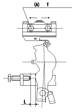
Microswitch adjustment
1.Fix the control lever so that the distance between the control lever and the idling stopper bolt is L (control lever position: a).
2. In the above condition, adjust the installation position of the microswitch so that so that it turns OFF.
Must change from ON to OFF at L1. [Lever angle b (from idle).]
(A): microswitch fixing bolt
----------
L=6.0mm L1=5.6~6.4mm a=14deg b=13~15deg
----------
T=2~3N-m(0.2~0.3kgf-m) L=6.0mm
----------
L=6.0mm L1=5.6~6.4mm a=14deg b=13~15deg
----------
T=2~3N-m(0.2~0.3kgf-m) L=6.0mm
0000001901 V-FICD ADJUSTMENT
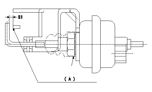
Adjustment of the V-FICD
1. Adjust the actuator rod to obtain S1.
2. Apply negative pressure P1 kPa {P2 mmHg} to the actuator and confirm that it moves through its full stroke.
(A) Control lever (Idling position)
----------
S1=1+1mm P1=-53.3kPa P2=-400mmHg
----------
S1=1+1mm
----------
S1=1+1mm P1=-53.3kPa P2=-400mmHg
----------
S1=1+1mm
Information:
Connector Contact Description for the Exhaust Particulate Filter
Table 1 describes the necessary electronic connections to the ECM.
Table 1
Pin Number Description Pin Number Description
J1-1 No Connection J1-36 Exhaust Pressure Active Analog Input 1
J1-2 No Connection J1-37 Exhaust Temperature Active Analog Input 2
J1-3 No Connection J1-38 Alarm Data Link
J1-4 RS-485 TX + J1-39 No Connection
J1-5 RS-485 TX - J1-40 No Connection
J1-6 RS-485 Shield J1-41 CAN Port 2 Low
J1-7 PWM/Freq/STG 9 J1-42 CAN Port 1 Shield
J1-8 CDL/ATA + J1-43 RS-232 Port 2 GND
J1-9 CDL/ATA - J1-44 PWM/Freq/STG 13
J1-10 PWM/Freq/STG 10 J1-45 STG 1
J1-11 No Connection J1-46 STG 2
J-12 No Connection J1-47 STG 3
J-13 RS-232 Port 1 TX J1-48 CAN Port 2 Shield
J-14 No Connection J1-49 PWM/Freq/STG 7
J-15 No Connection J1-50 CAN Port 1 High
J-16 No Connection J1-51 PWM/Freq/STG 8
J-17 RS-485 RX + J-52 + Battery
J-18 RS-485 RX - J-53 + Battery
J1-19 UPS Backup Battery (12V) J1-54 R-Terminal
J1-20 PWM/Freq/STG 11 J1-55 STG 4
J1-21 No Connection J1-56 PWM/STG 5
J1-22 RS-232 Port 1 RX J1-57 PWM/STG 6
J1-23 RS-232 Port 1 DTR J1=58 System Status LED (300mA Sinking Driver)
J1-24 No Connection J1-59 System Problem LED (300mA Sinking Driver 2)
J1-25 No Connection J1-60 Over Press LED (300mA Sinking Driver 3)
J1-26 PWM/Freq/STG 14 J1-61 Over Temp LED (300mA Sinking Driver 4)
J1-27 RS-232 Port 2 TX J1-62 RS-232 Port 3 TX
J1-28 PWM/Freq/STG 12 J1-63 RS-232 Port 3 RX
J1-29 No Connection J1-64 RS-232 Port 3 GND
J1-30 RS-232 Port 1 DCD J1-65 - Battery
J1-31 RS-232 Port 1 GND J1-66 STB 1
J1-32 No Connection J1-67 - Battery
J1-33 CAN Port 2 High J1-68 Aux +5V Supply
J1-34 CAN Port 1 Low J1-69 Aux Supply Return
J1-35 RS-232 Port RX J1-70 Keyswitch