Information injection-pump assembly
ZEXEL
104741-1381
1047411381
ISUZU
8944694150
8944694150
Rating:
Cross reference number
ZEXEL
104741-1381
1047411381
ISUZU
8944694150
8944694150
Zexel num
Bosch num
Firm num
Name
104741-1381
8944694150 ISUZU
INJECTION-PUMP ASSEMBLY
4JB1CDT *
4JB1CDT *
Calibration Data:
Adjustment conditions
Test oil
1404 Test oil ISO4113orSAEJ967d
1404 Test oil ISO4113orSAEJ967d
Test oil temperature
degC
45
45
50
Nozzle
105000-2010
Bosch type code
NP-DN12SD12TT
Nozzle holder
105780-2080
Opening pressure
MPa
14.7
14.7
15.19
Opening pressure
kgf/cm2
150
150
155
Injection pipe
Inside diameter - outside diameter - length (mm) mm 2-6-840
Inside diameter - outside diameter - length (mm) mm 2-6-840
Transfer pump pressure
kPa
20
20
20
Transfer pump pressure
kgf/cm2
0.2
0.2
0.2
Direction of rotation (viewed from drive side)
Right R
Right R
Injection timing adjustment
Pump speed
r/min
900
900
900
Boost pressure
kPa
45.3
44
46.6
Boost pressure
mmHg
340
330
350
Average injection quantity
mm3/st.
56
55.5
56.5
Difference in delivery
mm3/st.
4.5
Basic
*
Oil temperature
degC
50
48
52
Remarks
CBS
CBS
Injection timing adjustment_02
Pump speed
r/min
1150
1150
1150
Boost pressure
kPa
80
78.7
81.3
Boost pressure
mmHg
600
590
610
Average injection quantity
mm3/st.
66.1
65.6
66.6
Difference in delivery
mm3/st.
3.5
Basic
*
Oil temperature
degC
50
48
52
Remarks
Full
Full
Injection timing adjustment_03
Pump speed
r/min
500
500
500
Boost pressure
kPa
0
0
0
Boost pressure
mmHg
0
0
0
Average injection quantity
mm3/st.
39.9
36.4
43.4
Oil temperature
degC
48
46
50
Injection timing adjustment_04
Pump speed
r/min
750
750
750
Boost pressure
kPa
27.3
26
28.6
Boost pressure
mmHg
205
195
215
Average injection quantity
mm3/st.
46.4
46.4
46.4
Oil temperature
degC
50
48
52
Injection timing adjustment_05
Pump speed
r/min
900
900
900
Boost pressure
kPa
45.3
44
46.6
Boost pressure
mmHg
340
330
350
Average injection quantity
mm3/st.
56
55
57
Basic
*
Oil temperature
degC
50
48
52
Injection timing adjustment_06
Pump speed
r/min
1150
1150
1150
Boost pressure
kPa
80
78.7
81.3
Boost pressure
mmHg
600
590
610
Average injection quantity
mm3/st.
66.1
65.1
67.1
Difference in delivery
mm3/st.
3.5
Basic
*
Oil temperature
degC
50
48
52
Injection timing adjustment_07
Pump speed
r/min
1900
1900
1900
Boost pressure
kPa
80
78.7
81.3
Boost pressure
mmHg
600
590
610
Average injection quantity
mm3/st.
64.2
58.7
69.7
Difference in delivery
mm3/st.
5.5
Oil temperature
degC
50
48
52
Injection quantity adjustment
Pump speed
r/min
2300
2300
2300
Boost pressure
kPa
80
78.7
81.3
Boost pressure
mmHg
600
590
610
Average injection quantity
mm3/st.
17.9
14.9
20.9
Difference in delivery
mm3/st.
4.5
Basic
*
Oil temperature
degC
52
50
54
Injection quantity adjustment_02
Pump speed
r/min
2400
2400
2400
Boost pressure
kPa
80
78.7
81.3
Boost pressure
mmHg
600
590
610
Average injection quantity
mm3/st.
8
Oil temperature
degC
52
50
54
Injection quantity adjustment_03
Pump speed
r/min
2300
2300
2300
Boost pressure
kPa
80
78.7
81.3
Boost pressure
mmHg
600
590
610
Average injection quantity
mm3/st.
17.9
14.9
20.9
Difference in delivery
mm3/st.
4.5
Oil temperature
degC
52
50
54
Governor adjustment
Pump speed
r/min
385
385
385
Boost pressure
kPa
0
0
0
Boost pressure
mmHg
0
0
0
Average injection quantity
mm3/st.
6
4
8
Difference in delivery
mm3/st.
2
Basic
*
Oil temperature
degC
48
46
50
Governor adjustment_02
Pump speed
r/min
385
385
385
Boost pressure
kPa
0
0
0
Boost pressure
mmHg
0
0
0
Average injection quantity
mm3/st.
6
4
8
Difference in delivery
mm3/st.
2
Oil temperature
degC
48
46
50
Timer adjustment
Pump speed
r/min
100
100
100
Boost pressure
kPa
0
0
0
Boost pressure
mmHg
0
0
0
Average injection quantity
mm3/st.
75
75
115
Basic
*
Oil temperature
degC
48
46
50
Remarks
Full
Full
Timer adjustment_02
Pump speed
r/min
100
100
100
Boost pressure
kPa
0
0
0
Boost pressure
mmHg
0
0
0
Average injection quantity
mm3/st.
92.5
70
115
Oil temperature
degC
48
46
50
Speed control lever angle
Pump speed
r/min
385
385
385
Boost pressure
kPa
0
0
0
Boost pressure
mmHg
0
0
0
Average injection quantity
mm3/st.
0
0
0
Oil temperature
degC
48
46
50
Remarks
Magnet OFF at idling position
Magnet OFF at idling position
0000000901
Pump speed
r/min
1700
1700
1700
Boost pressure
kPa
0
0
0
Boost pressure
mmHg
0
0
0
Oil temperature
degC
50
48
52
Remarks
MEASURE
MEASURE
Stop lever angle
Pump speed
r/min
1700
1700
1700
Boost pressure
kPa
0
0
0
Boost pressure
mmHg
0
0
0
Pressure with S/T OFF
kPa
530
510
550
Pressure with S/T OFF
kgf/cm2
5.4
5.2
5.6
Basic
*
Oil temperature
degC
50
48
52
Stop lever angle_02
Pump speed
r/min
1700
1700
1700
Boost pressure
kPa
0
0
0
Boost pressure
mmHg
0
0
0
Pressure with S/T OFF
kPa
530
510
550
Pressure with S/T OFF
kgf/cm2
5.4
5.2
5.6
Basic
*
Oil temperature
degC
50
48
52
Stop lever angle_03
Pump speed
r/min
2000
2000
2000
Boost pressure
kPa
0
0
0
Boost pressure
mmHg
0
0
0
Pressure with S/T OFF
kPa
706
667
745
Pressure with S/T OFF
kgf/cm2
7.2
6.8
7.6
Oil temperature
degC
50
48
52
0000001101
Pump speed
r/min
1700
1700
1700
Boost pressure
kPa
0
0
0
Boost pressure
mmHg
0
0
0
Timer stroke with S/T OFF
mm
4.3
4.1
4.5
Basic
*
Oil temperature
degC
50
48
52
_02
Pump speed
r/min
820
820
820
Boost pressure
kPa
0
0
0
Boost pressure
mmHg
0
0
0
Timer stroke with S/T ON
mm
0.5
0.5
0.5
Oil temperature
degC
50
48
52
_03
Pump speed
r/min
1470
1470
1470
Boost pressure
kPa
0
0
0
Boost pressure
mmHg
0
0
0
Timer stroke with S/T OFF
mm
0.5
0.5
0.5
Oil temperature
degC
50
48
52
_04
Pump speed
r/min
1700
1700
1700
Boost pressure
kPa
0
0
0
Boost pressure
mmHg
0
0
0
Timer stroke with S/T OFF
mm
4.3
4.1
4.5
Basic
*
Oil temperature
degC
50
48
52
_05
Pump speed
r/min
2000
2000
2000
Boost pressure
kPa
0
0
0
Boost pressure
mmHg
0
0
0
Timer stroke with S/T OFF
mm
9.4
9.1
9.8
Oil temperature
degC
50
48
52
0000001201
Max. applied voltage
V
8
8
8
Test voltage
V
13
12
14
Timing setting
K dimension
mm
2.8
2.7
2.9
KF dimension
mm
5.5
5.4
5.6
MS dimension
mm
1
0.9
1.1
BCS stroke
mm
4.2
4
4.4
Pre-stroke
mm
0.45
0.43
0.47
Control lever angle alpha
deg.
18
14
22
Control lever angle beta
deg.
37
32
42
Test data Ex:
0000001801 MICROSWITCH ADJUSTMENT
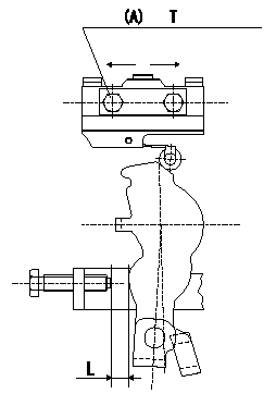
Microswitch adjustment
1.Fix the control lever so that the distance between the control lever and the idling stopper bolt is L (control lever position: a).
2. In the above condition, adjust the installation position of the microswitch so that so that it turns OFF.
(A) = microswitch fixing bolt
----------
L=6.0mm a=14deg
----------
T=2~3N-m{0.2~0.3kgf-m} L=6.0+-0.2mm
----------
L=6.0mm a=14deg
----------
T=2~3N-m{0.2~0.3kgf-m} L=6.0+-0.2mm
0000001901 V-FICD ADJUSTMENT
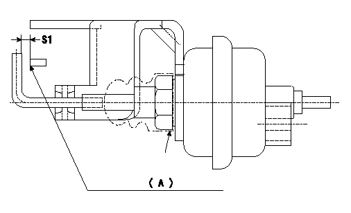
Adjustment of the V-FICD
1. Adjust the actuator rod to obtain S1.
2. Apply negative pressure P1 kPa {P2 mmHg} to the actuator and confirm that it moves through its full stroke.
(A) Control lever (Idling position)
----------
S1=1+1mm P1=-53.3kPa P2=-400mmHg
----------
S1=1+1mm
----------
S1=1+1mm P1=-53.3kPa P2=-400mmHg
----------
S1=1+1mm
Information:
Clean any machining debris that may be on the inside of the flywheel housing.Ensure that the debris guard is clean. A clean guard will ensure that no machining debris falls into the engine when the debris guard is removed.
Remove the debris guard from the inside of the flywheel housing.Install the Pipe Adapters and Sensors
Use 12 5P-2424 Bolts and 118-0275 Washers in order to install wheel (1) onto the cam gear.
Illustration 24 g01323683
(K) Installation guide for the pipe adapters
Illustration 25 g01323672
(1) 284-8910 Wheel
Install the installation guide for the pipe adapters.The installation guide must be installed on the evenly spaced teeth of wheel (1). Refer to Illustration 25.
Illustration 26 g01323669
(2) Fabricated pipe adapters
Install the top and the bottom pipe adapters (2) that were fabricated from the design in Illustration 6.
Use 7M-7456 Bearing Mount Compound to coat the outside of pipe adapter (2) .
Ensure that the adapter is properly aligned with the machined hole.
Illustration 27 g01323703
(L) Bushing driver (2) Pipe adapter
Illustration 28 g01323665
Pipe adapter (2) in contact with installation guide (K)
Use bushing driver (L) to install pipe adapters (2) .Continue installing the pipe adapters until the adapters contact the installation guide. The guide will not wiggle when the adapters are properly installed. Refer to Illustrations 27 and 28.
Remove the installation guide.
Illustration 29 g01324920
Correct alignment of the center pole of the speed sensor (3) Center pole of the speed sensor
Inspect the hole in pipe adapters (2) .The tooth of wheel (1) must be in the center of the hole in the pipe adapter. In order to ensure that the speed sensor will operate correctly, the center of the speed sensor must align with a tooth on wheel (1). Refer to Illustration 29 for an example of the correct alignment.
Illustration 30 g01323661
183-8597 Speed Sensor Gp
Illustration 31 g01323666
Speed sensors (5) Primary speed sensor (6) Secondary speed sensor
Install 3K-0360 O-Ring Seals with primary speed sensor (5) and secondary speed sensor (6) . 183-8597 Speed Sensor Gp Torque ... 37 4 N m (27 3 lb ft) Clearance between tip of sensor and the wheel ... 0.750 mm to 2.000 mm (0.0295 inch to 0.0787 inch)Note: Note the position of extra tooth (7) in relation to primary speed sensor (5) .Note: The 284-8909 Camshaft Gear may need repositioned in order to adjust the position of wheel (1).
Illustration 32 g01323706
Typical example of wheel (1) in standard rotation (7) Extra tooth
Illustration 33 g01323668
Typical example of wheel (1) in reverse rotation
Adjust the 284-8910 Wheel .
Align the first tooth after extra tooth (7) with the center of the primary speed sensor.Refer to Illustration 32.
Torque the bolts to 120 N m (89 lb ft).
Recheck the alignment of the first tooth after extra tooth (7) and the primary speed sensor.
Install the 240-9736 Cylinder Block Cover Gp .
Use 0S-1594 Bolts and 3V-3308 Hard Washers in order to install the two 4B-3140 Covers and the 1W-1960 Gaskets onto the front housing of the engine.
Use 3B-1915 Bolts and 3V-3308 Hard Washers in order to install the 7E-5420 Cover and
Have questions with 104741-1381?
Group cross 104741-1381 ZEXEL
Isuzu
104741-1381
8944694150
INJECTION-PUMP ASSEMBLY
4JB1CDT
4JB1CDT