Information injection-pump assembly
ZEXEL
104741-1380
1047411380
ISUZU
8944528170
8944528170

Rating:
Cross reference number
ZEXEL
104741-1380
1047411380
ISUZU
8944528170
8944528170
Zexel num
Bosch num
Firm num
Name
Calibration Data:
Adjustment conditions
Test oil
1404 Test oil ISO4113orSAEJ967d
1404 Test oil ISO4113orSAEJ967d
Test oil temperature
degC
45
45
50
Nozzle
105000-2010
Bosch type code
NP-DN12SD12TT
Nozzle holder
105780-2080
Opening pressure
MPa
14.7
14.7
15.19
Opening pressure
kgf/cm2
150
150
155
Injection pipe
Inside diameter - outside diameter - length (mm) mm 2-6-840
Inside diameter - outside diameter - length (mm) mm 2-6-840
Transfer pump pressure
kPa
20
20
20
Transfer pump pressure
kgf/cm2
0.2
0.2
0.2
Direction of rotation (viewed from drive side)
Right R
Right R
Injection timing adjustment
Pump speed
r/min
900
900
900
Boost pressure
kPa
45.3
44
46.6
Boost pressure
mmHg
340
330
350
Average injection quantity
mm3/st.
55
54.5
55.5
Difference in delivery
mm3/st.
4.5
Basic
*
Oil temperature
degC
50
48
52
Remarks
CBS
CBS
Injection timing adjustment_02
Pump speed
r/min
1150
1150
1150
Boost pressure
kPa
73.3
72
74.6
Boost pressure
mmHg
550
540
560
Average injection quantity
mm3/st.
66.1
65.6
66.6
Difference in delivery
mm3/st.
3.5
Basic
*
Oil temperature
degC
50
48
52
Remarks
Full
Full
Injection timing adjustment_03
Pump speed
r/min
500
500
500
Boost pressure
kPa
0
0
0
Boost pressure
mmHg
0
0
0
Average injection quantity
mm3/st.
39.9
36.4
43.4
Oil temperature
degC
48
46
50
Injection timing adjustment_04
Pump speed
r/min
750
750
750
Boost pressure
kPa
27.3
26
28.6
Boost pressure
mmHg
205
195
215
Average injection quantity
mm3/st.
46.4
46.4
46.4
Oil temperature
degC
50
48
52
Injection timing adjustment_05
Pump speed
r/min
900
900
900
Boost pressure
kPa
45.3
44
46.6
Boost pressure
mmHg
340
330
350
Average injection quantity
mm3/st.
55
54
56
Basic
*
Oil temperature
degC
50
48
52
Injection timing adjustment_06
Pump speed
r/min
1150
1150
1150
Boost pressure
kPa
73.3
72
74.6
Boost pressure
mmHg
550
540
560
Average injection quantity
mm3/st.
66.1
65.1
67.1
Difference in delivery
mm3/st.
3.5
Basic
*
Oil temperature
degC
50
48
52
Injection timing adjustment_07
Pump speed
r/min
1900
1900
1900
Boost pressure
kPa
80
78.7
81.3
Boost pressure
mmHg
600
590
610
Average injection quantity
mm3/st.
64.2
60.2
68.2
Difference in delivery
mm3/st.
5.5
Oil temperature
degC
50
48
52
Injection quantity adjustment
Pump speed
r/min
2300
2300
2300
Boost pressure
kPa
80
78.7
81.3
Boost pressure
mmHg
600
590
610
Average injection quantity
mm3/st.
17.9
14.9
20.9
Difference in delivery
mm3/st.
4.5
Basic
*
Oil temperature
degC
52
50
54
Injection quantity adjustment_02
Pump speed
r/min
2400
2400
2400
Boost pressure
kPa
80
78.7
81.3
Boost pressure
mmHg
600
590
610
Average injection quantity
mm3/st.
8
Oil temperature
degC
52
50
54
Injection quantity adjustment_03
Pump speed
r/min
2300
2300
2300
Boost pressure
kPa
80
78.7
81.3
Boost pressure
mmHg
600
590
610
Average injection quantity
mm3/st.
17.9
14.9
20.9
Difference in delivery
mm3/st.
4.5
Oil temperature
degC
52
50
54
Governor adjustment
Pump speed
r/min
385
385
385
Boost pressure
kPa
0
0
0
Boost pressure
mmHg
0
0
0
Average injection quantity
mm3/st.
6
4
8
Difference in delivery
mm3/st.
2
Basic
*
Oil temperature
degC
48
46
50
Governor adjustment_02
Pump speed
r/min
385
385
385
Boost pressure
kPa
0
0
0
Boost pressure
mmHg
0
0
0
Average injection quantity
mm3/st.
6
4
8
Difference in delivery
mm3/st.
2
Oil temperature
degC
48
46
50
Timer adjustment
Pump speed
r/min
100
100
100
Boost pressure
kPa
0
0
0
Boost pressure
mmHg
0
0
0
Average injection quantity
mm3/st.
75
75
115
Basic
*
Oil temperature
degC
48
46
50
Remarks
Full
Full
Timer adjustment_02
Pump speed
r/min
100
100
100
Boost pressure
kPa
0
0
0
Boost pressure
mmHg
0
0
0
Average injection quantity
mm3/st.
92.5
70
115
Oil temperature
degC
48
46
50
Speed control lever angle
Pump speed
r/min
385
385
385
Boost pressure
kPa
0
0
0
Boost pressure
mmHg
0
0
0
Average injection quantity
mm3/st.
0
0
0
Oil temperature
degC
48
46
50
Remarks
Magnet OFF at idling position
Magnet OFF at idling position
0000000901
Pump speed
r/min
1700
1700
1700
Boost pressure
kPa
0
0
0
Boost pressure
mmHg
0
0
0
Oil temperature
degC
50
48
52
Remarks
MEASURE
MEASURE
Stop lever angle
Pump speed
r/min
1700
1700
1700
Boost pressure
kPa
0
0
0
Boost pressure
mmHg
0
0
0
Pressure with S/T OFF
kPa
441
421
461
Pressure with S/T OFF
kgf/cm2
4.5
4.3
4.7
Basic
*
Oil temperature
degC
50
48
52
Stop lever angle_02
Pump speed
r/min
1700
1700
1700
Boost pressure
kPa
0
0
0
Boost pressure
mmHg
0
0
0
Pressure with S/T OFF
kPa
441
421
461
Pressure with S/T OFF
kgf/cm2
4.5
4.3
4.7
Basic
*
Oil temperature
degC
50
48
52
Stop lever angle_03
Pump speed
r/min
2000
2000
2000
Boost pressure
kPa
0
0
0
Boost pressure
mmHg
0
0
0
Pressure with S/T OFF
kPa
569
530
608
Pressure with S/T OFF
kgf/cm2
5.8
5.4
6.2
Oil temperature
degC
50
48
52
0000001101
Pump speed
r/min
1700
1700
1700
Boost pressure
kPa
0
0
0
Boost pressure
mmHg
0
0
0
Timer stroke with S/T OFF
mm
4.3
4.1
4.5
Basic
*
Oil temperature
degC
50
48
52
_02
Pump speed
r/min
820
820
820
Boost pressure
kPa
0
0
0
Boost pressure
mmHg
0
0
0
Timer stroke with S/T ON
mm
0.5
0.5
0.5
Oil temperature
degC
50
48
52
_03
Pump speed
r/min
1470
1470
1470
Boost pressure
kPa
0
0
0
Boost pressure
mmHg
0
0
0
Timer stroke with S/T OFF
mm
0.5
0.5
0.5
Oil temperature
degC
50
48
52
_04
Pump speed
r/min
1700
1700
1700
Boost pressure
kPa
0
0
0
Boost pressure
mmHg
0
0
0
Timer stroke with S/T OFF
mm
4.3
4.1
4.5
Basic
*
Oil temperature
degC
50
48
52
_05
Pump speed
r/min
2000
2000
2000
Boost pressure
kPa
0
0
0
Boost pressure
mmHg
0
0
0
Timer stroke with S/T OFF
mm
9.4
9.1
9.8
Oil temperature
degC
50
48
52
0000001201
Max. applied voltage
V
8
8
8
Test voltage
V
13
12
14
Timing setting
K dimension
mm
2.8
2.7
2.9
KF dimension
mm
5.5
5.4
5.6
MS dimension
mm
1
0.9
1.1
BCS stroke
mm
4.2
4
4.4
Pre-stroke
mm
0.45
0.43
0.47
Control lever angle alpha
deg.
18
14
22
Control lever angle beta
deg.
37
32
42
Test data Ex:
0000001801 MICROSWITCH ADJUSTMENT
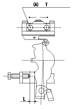
Microswitch adjustment
1.Fix the control lever so that the distance between the control lever and the idling stopper bolt is L (control lever position: a).
2. In the above condition, adjust the installation position of the microswitch so that so that it turns OFF.
(A) = microswitch fixing bolt
----------
L=6.0mm a=14deg
----------
T=2~3N-m(0.2~0.3kgf-m) L=6.0mm
----------
L=6.0mm a=14deg
----------
T=2~3N-m(0.2~0.3kgf-m) L=6.0mm
0000001901 V-FICD ADJUSTMENT
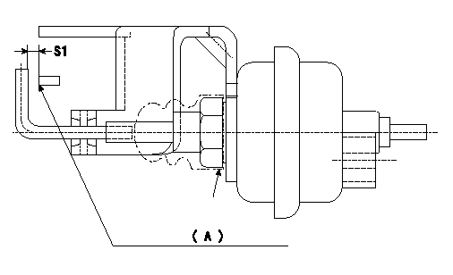
Adjustment of the V-FICD
1. Adjust the actuator rod to obtain S1.
2. Apply negative pressure P1 kPa {P2 mmHg} to the actuator and confirm that it moves through its full stroke.
(A) Control lever (Idling position)
----------
S1=1+1mm P1=-53.3kPa P2=-400mmHg
----------
S1=1+1mm
----------
S1=1+1mm P1=-53.3kPa P2=-400mmHg
----------
S1=1+1mm
Information:
Introduction
The problem that is identified below does not have a known permanent solution. Until a permanent solution is known, use the solution that is identified below.Problem
Some of the 3408E engines and 3412E engines in the above listed machines may experience hard starting or low power due to oil that is leaking past the poppet valve in the injector. The oil leakage is caused by the operating conditions at either low idle or high idle. Excessive oil leakage can reduce actuation pressure to the fuel injector. This may prevent fuel injection.Solution
Electrical shock hazard. The electronic unit injector system uses 90-120 volts.
Follow the proper troubleshooting procedure for the correct engine. If the problem is not located and the symptoms that are listed above continue, remove the engine valve covers. Electrically disable the injectors. Crank the engine. Watch the spill ports of the injector for oil leakage. A small amount of oil leakage is acceptable. A continuous stream of oil may mean leakage from the poppet valve. Excessive leakage from the poppet valve may prevent fuel injection.Note: Normal oil pressure during cranking should be 5 MPa (725 psi). Oil pressure below 5 MPa (725 psi) may indicate excessive oil leakage in injectors. Do not replace the oil pump. Service personnel should replace the injectors that have a continuous flow of oil from the oil ports. Injectors that have a continuous flow of oil and injectors that are within the guidelines of warranty can be returned. Injectors that do not have a continuous flow of oil should not be replaced. Injectors that do not have a continuous flow of oil should not be returned.Note: For additional information on the operation of Hydraulic Electronic Unit Injectors HEUI, refer to CD, RENR1390.
Illustration 1 g01308874
(1) Oil drain portThe oil drain ports are located underneath the solenoid. This will direct the oil flow downward. Some oil may also leak from the rectangular slots at the side of the solenoid. Excess oil leakage will still be visible on the cylinder head.