Information injection-pump assembly
ZEXEL
104741-1370
1047411370
ISUZU
8944528010
8944528010
Rating:
Cross reference number
ZEXEL
104741-1370
1047411370
ISUZU
8944528010
8944528010
Zexel num
Bosch num
Firm num
Name
Calibration Data:
Adjustment conditions
Test oil
1404 Test oil ISO4113orSAEJ967d
1404 Test oil ISO4113orSAEJ967d
Test oil temperature
degC
45
45
50
Nozzle
105000-2010
Bosch type code
NP-DN12SD12TT
Nozzle holder
105780-2080
Opening pressure
MPa
14.7
14.7
15.19
Opening pressure
kgf/cm2
150
150
155
Injection pipe
Inside diameter - outside diameter - length (mm) mm 2-6-840
Inside diameter - outside diameter - length (mm) mm 2-6-840
Transfer pump pressure
kPa
20
20
20
Transfer pump pressure
kgf/cm2
0.2
0.2
0.2
Direction of rotation (viewed from drive side)
Left L
Left L
Injection timing adjustment
Pump speed
r/min
1150
1150
1150
Average injection quantity
mm3/st.
40.6
40.1
41.1
Difference in delivery
mm3/st.
3.5
Basic
*
Oil temperature
degC
50
48
52
Injection timing adjustment_02
Pump speed
r/min
500
500
500
Average injection quantity
mm3/st.
36.2
32.2
40.2
Oil temperature
degC
48
46
50
Injection timing adjustment_03
Pump speed
r/min
750
750
750
Average injection quantity
mm3/st.
35.6
33.1
38.1
Oil temperature
degC
50
48
52
Injection timing adjustment_04
Pump speed
r/min
1150
1150
1150
Average injection quantity
mm3/st.
40.6
39.6
41.6
Difference in delivery
mm3/st.
3.5
Basic
*
Oil temperature
degC
50
48
52
Injection timing adjustment_05
Pump speed
r/min
1500
1500
1500
Average injection quantity
mm3/st.
40.5
40.5
40.5
Oil temperature
degC
50
48
52
Injection timing adjustment_06
Pump speed
r/min
1900
1900
1900
Average injection quantity
mm3/st.
41.1
41.1
41.1
Oil temperature
degC
50
48
52
Injection timing adjustment_07
Pump speed
r/min
2000
2000
2000
Average injection quantity
mm3/st.
40.1
36.6
43.6
Difference in delivery
mm3/st.
5.5
Oil temperature
degC
50
48
52
Injection quantity adjustment
Pump speed
r/min
2300
2300
2300
Average injection quantity
mm3/st.
24.1
21.1
27.1
Difference in delivery
mm3/st.
3.5
Basic
*
Oil temperature
degC
52
50
54
Injection quantity adjustment_02
Pump speed
r/min
2500
2500
2500
Average injection quantity
mm3/st.
6
Oil temperature
degC
55
52
58
Injection quantity adjustment_03
Pump speed
r/min
2300
2300
2300
Average injection quantity
mm3/st.
24.1
21.1
27.1
Difference in delivery
mm3/st.
3.5
Oil temperature
degC
52
50
54
Governor adjustment
Pump speed
r/min
375
375
375
Average injection quantity
mm3/st.
6
4
8
Difference in delivery
mm3/st.
3
Basic
*
Oil temperature
degC
48
46
50
Governor adjustment_02
Pump speed
r/min
375
375
375
Average injection quantity
mm3/st.
6
4
8
Difference in delivery
mm3/st.
2
Oil temperature
degC
48
46
50
Timer adjustment
Pump speed
r/min
100
100
100
Average injection quantity
mm3/st.
60
60
100
Basic
*
Oil temperature
degC
48
46
50
Timer adjustment_02
Pump speed
r/min
100
100
100
Average injection quantity
mm3/st.
80
60
100
Oil temperature
degC
48
46
50
Speed control lever angle
Pump speed
r/min
375
375
375
Average injection quantity
mm3/st.
0
0
0
Oil temperature
degC
48
46
50
Remarks
Magnet OFF at idling position
Magnet OFF at idling position
0000000901
Pump speed
r/min
1600
1600
1600
Oil temperature
degC
50
48
52
Remarks
MEASURE
MEASURE
Stop lever angle
Pump speed
r/min
1600
1600
1600
Pressure with S/T OFF
kPa
490
470
510
Pressure with S/T OFF
kgf/cm2
5
4.8
5.2
Basic
*
Oil temperature
degC
50
48
52
Stop lever angle_02
Pump speed
r/min
1600
1600
1600
Pressure with S/T OFF
kPa
490
470
510
Pressure with S/T OFF
kgf/cm2
5
4.8
5.2
Basic
*
Oil temperature
degC
50
48
52
Stop lever angle_03
Pump speed
r/min
2000
2000
2000
Pressure with S/T OFF
kPa
608
579
637
Pressure with S/T OFF
kgf/cm2
6.2
5.9
6.5
Oil temperature
degC
50
48
52
0000001101
Pump speed
r/min
1600
1600
1600
Timer stroke with S/T OFF
mm
4.8
4.6
5
Basic
*
Oil temperature
degC
50
48
52
_02
Pump speed
r/min
770
770
770
Timer stroke with S/T ON
mm
0.5
0.5
0.5
Oil temperature
degC
50
48
52
_03
Pump speed
r/min
1020
1020
1020
Timer stroke with S/T OFF
mm
0.5
0.5
0.5
Oil temperature
degC
50
48
52
_04
Pump speed
r/min
1600
1600
1600
Timer stroke with S/T OFF
mm
4.8
4.6
5
Basic
*
Oil temperature
degC
50
48
52
_05
Pump speed
r/min
2000
2000
2000
Timer stroke with S/T OFF
mm
7.8
7.5
8.2
Oil temperature
degC
50
48
52
0000001201
Max. applied voltage
V
8
8
8
Test voltage
V
13
12
14
Timing setting
K dimension
mm
2.8
2.7
2.9
KF dimension
mm
5.5
5.4
5.6
MS dimension
mm
1
0.9
1.1
Pre-stroke
mm
0.45
0.43
0.47
Control lever angle alpha
deg.
18
14
22
Control lever angle beta
deg.
37
32
42
Test data Ex:
0000001801 MICROSWITCH ADJUSTMENT
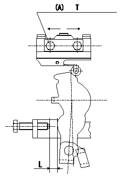
Microswitch adjustment
1.Fix the control lever so that the distance between the control lever and the idling stopper bolt is L (control lever position: a).
2. In the above condition, adjust the installation position of the microswitch so that so that it turns OFF.
(A) = microswitch fixing bolt
----------
L=6.0mm a=14deg
----------
T=2~3N-m(0.2~0.3kgf-m) L=6.0mm
----------
L=6.0mm a=14deg
----------
T=2~3N-m(0.2~0.3kgf-m) L=6.0mm
0000001901 V-FICD ADJUSTMENT
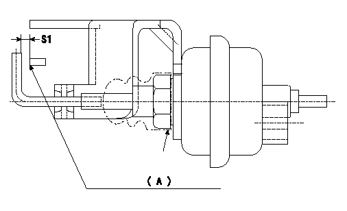
Adjustment of the V-FICD
1. Adjust the actuator rod to obtain S1.
2. Apply negative pressure P1 kPa {P2 mmHg} to the actuator and confirm that it moves through its full stroke.
(A) Control lever (Idling position)
----------
S1=1+1mm P1=-53.3kPa P2=-400mmHg
----------
S1=1+1mm
----------
S1=1+1mm P1=-53.3kPa P2=-400mmHg
----------
S1=1+1mm
Information:
Introduction
The following special instructions must be used to test for a crack in the Diesel Particulate Filter (DPF). Do not perform any procedure that is outlined in this Special Instruction until you have read and understand the information that is contained in this document.Required Tools
Table 1
Required Tools
Tool Part Number Part Description Qty
A 380-5200 Tool Kit 1
B 366-7782 Attenuator 1 Testing Procedure
Perform a "Manual Diesel Particulate Filter Regeneration" using the electronic service tool.
After the manual DPF regeneration is complete, operate the engine at 1800 rpm for a MINIMUM of 20 minutes to stabilize the DPF temperatures.Note: The engine must maintain a steady speed for the entire duration of the test.
Hot engine components can cause injury from burns. Before performing maintenance on the engine, allow the engine and the components to cool.
Illustration 1 g02597531
Typical example (1) DPF Outlet Cap (2) Filter Paper (3) Hose Assembly (4) Air Pump
Illustration 2 g03655197
Typical example
Stop the engine. Disconnect harness assembly from both soot antennae. Remove outlet soot antenna (5). Refer to