Information injection-pump assembly
ZEXEL
104741-1330
1047411330
ISUZU
8944207311
8944207311
Rating:
Cross reference number
ZEXEL
104741-1330
1047411330
ISUZU
8944207311
8944207311
Zexel num
Bosch num
Firm num
Name
Calibration Data:
Adjustment conditions
Test oil
1404 Test oil ISO4113orSAEJ967d
1404 Test oil ISO4113orSAEJ967d
Test oil temperature
degC
45
45
50
Nozzle
105000-2010
Bosch type code
NP-DN12SD12TT
Nozzle holder
105780-2080
Opening pressure
MPa
14.7
14.7
15.19
Opening pressure
kgf/cm2
150
150
155
Injection pipe
Inside diameter - outside diameter - length (mm) mm 2-6-840
Inside diameter - outside diameter - length (mm) mm 2-6-840
Transfer pump pressure
kPa
20
20
20
Transfer pump pressure
kgf/cm2
0.2
0.2
0.2
Direction of rotation (viewed from drive side)
Left L
Left L
Injection timing adjustment
Pump speed
r/min
1000
1000
1000
Average injection quantity
mm3/st.
44.1
43.6
44.6
Difference in delivery
mm3/st.
3.5
Basic
*
Injection timing adjustment_02
Pump speed
r/min
2250
2250
2250
Average injection quantity
mm3/st.
16.1
12.6
19.6
Injection timing adjustment_03
Pump speed
r/min
2000
2000
2000
Average injection quantity
mm3/st.
43.8
40.8
46.8
Injection timing adjustment_04
Pump speed
r/min
1600
1600
1600
Average injection quantity
mm3/st.
48.4
45.9
50.9
Injection timing adjustment_05
Pump speed
r/min
1000
1000
1000
Average injection quantity
mm3/st.
44.1
43.1
45.1
Injection timing adjustment_06
Pump speed
r/min
700
700
700
Average injection quantity
mm3/st.
37.9
35.4
40.4
Injection timing adjustment_07
Pump speed
r/min
500
500
500
Average injection quantity
mm3/st.
36.3
32.8
39.8
Injection quantity adjustment
Pump speed
r/min
2250
2250
2250
Average injection quantity
mm3/st.
16.1
13.1
19.1
Difference in delivery
mm3/st.
4.5
Basic
*
Injection quantity adjustment_02
Pump speed
r/min
2350
2350
2350
Average injection quantity
mm3/st.
12.1
Governor adjustment
Pump speed
r/min
385
385
385
Average injection quantity
mm3/st.
7.7
5.7
9.7
Difference in delivery
mm3/st.
2
Basic
*
Governor adjustment_02
Pump speed
r/min
385
385
385
Average injection quantity
mm3/st.
7.7
5.7
9.7
Governor adjustment_03
Pump speed
r/min
450
450
450
Average injection quantity
mm3/st.
5
Timer adjustment
Pump speed
r/min
100
100
100
Average injection quantity
mm3/st.
65
65
Basic
*
Speed control lever angle
Pump speed
r/min
385
385
385
Average injection quantity
mm3/st.
0
0
0
Remarks
Magnet OFF
Magnet OFF
0000000901
Pump speed
r/min
1600
1600
1600
Overflow quantity
cm3/min
429
300
558
Stop lever angle
Pump speed
r/min
1600
1600
1600
Pressure
kPa
539.5
520
559
Pressure
kgf/cm2
5.5
5.3
5.7
Basic
*
Stop lever angle_02
Pump speed
r/min
500
500
500
Pressure
kPa
108
108
Pressure
kgf/cm2
1.1
1.1
Stop lever angle_03
Pump speed
r/min
1200
1200
1200
Pressure
kPa
421.5
392
451
Pressure
kgf/cm2
4.3
4
4.6
Stop lever angle_04
Pump speed
r/min
1600
1600
1600
Pressure
kPa
539.5
520
559
Pressure
kgf/cm2
5.5
5.3
5.7
Stop lever angle_05
Pump speed
r/min
2000
2000
2000
Pressure
kPa
531.5
367
696
Pressure
kgf/cm2
6.8
6.5
7.1
0000001101
Pump speed
r/min
1600
1600
1600
Timer stroke
mm
5
4.8
5.2
Basic
*
_02
Pump speed
r/min
1080
1080
1080
Timer stroke
mm
0.5
0.5
0.5
_03
Pump speed
r/min
1200
1200
1200
Timer stroke
mm
1.8
1.3
2.3
_04
Pump speed
r/min
1600
1600
1600
Timer stroke
mm
5
4.7
5.3
_05
Pump speed
r/min
2000
2000
2000
Timer stroke
mm
7.85
7.4
8.3
0000001201
Max. applied voltage
V
8
8
8
Test voltage
V
13
12
14
0000001501
Pump speed
r/min
1000
1000
1000
Atmospheric pressure difference
kPa
-21.9
-22.6
-21.2
Atmospheric pressure difference
mmHg
-164
-169
-159
Decrease qty
mm3/st.
4.4
3.1
5.7
Basic
*
_02
Pump speed
r/min
1000
1000
1000
Atmospheric pressure difference
kPa
-21.9
-22.6
-21.2
Atmospheric pressure difference
mmHg
-164
-169
-159
Decrease qty
mm3/st.
4.4
2.4
6.4
Timing setting
K dimension
mm
2.8
2.7
2.9
KF dimension
mm
5
4.9
5.1
MS dimension
mm
1
0.9
1.1
Pre-stroke
mm
0.45
0.43
0.47
Control lever angle alpha
deg.
18
14
22
Control lever angle beta
deg.
37
32
42
Test data Ex:
0000001501 ANEROID COMPENSATOR
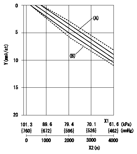
ACS adjustment
Full load injection quantity at high altitudes and ACS adjusting method
1. Full load injection quantity adjustment
(1)Remove the ACS cover and remove the bellows and adjusting shim.
(2)Perform all adjustments as per the adjustment standard except for ACS adjustment.
2. ACS adjustment
(1)Assemble the ACS cover, bellows and adjusting shim.
(2)At pump speed N1, adjust using a shim to obtain the decrease for the altitude shown in the table.
X1 = atmospheric pressure
X2 = altitude
Y = decrease quantity
(A) = adjustment value
(B) = test value
----------
N1=1000r/min
----------
----------
N1=1000r/min
----------
Information:
Introduction
The problem that is identified below does not have a known permanent solution. Until a permanent solution is known, use the solution that is identified below.Problem
The diesel exhaust fluid (DEF) quality sensors are susceptible to seeing the following fault codes.
Table 1
J1939 CDL Code Description
3516-2 3100-2 Aftertreatment #1 DEF Concentration: Erratic, Intermittent or Incorrect
3516-12 3100-12 Aftertreatment #1 DEF Concentration: Failure
3516-16 E1365 High Aftertreatment #1 DEF Concentration
3516-18 E1364 Low Aftertreatment #1 DEF Concentration Solution
The latest software available in SIS has improvements in it related to the DEF quality sensor and these fault codes.
Ensure that the latest engine and aftertreatment software is installed prior to any hardware replacements.
Ensure that the latest DCU software is installed ( 539-3577 Engine Software (24V DCU) or 539-3576 Engine Software (12V DCU)).
In addition to the troubleshooting for these fault codes in SIS web, ensure that DEF quality is checked with both a refractometer and the 466-8796 Test Strips as outlined in Diesel Exhaust Fluid Quality - Test procedure in SIS.
Keep the DEF tank full when machine/engine will not be operated for an extended period of time to help reduce manifold exposure to ammonia gases in the DEF tank.Have seen cases of contamination where the test strips will not detect it if contamination is not hydrocarbon-based. In these instances, the DEF will appear to be cloudy when doing a visual comparison to a good, clean DEF sample.While working through issues related to these particular fault codes, email Blunier_Derek_W to provide troubleshooting information and documentation as to what was found.Information to Provide
PSRPT with histograms
Application History File
All troubleshooting resultsIf the DEF manifold does get replaced, provide the following:
Dealer code
Workorder number
Serial number
Hours at repair
DEF sample collected from top level of tank to be returned along with the DEF manifoldA Send It Back (SIB) will be created to get the DEF manifold returned.Downloading an Application History File
Illustration 1 g06233931
Click the appropriate ECM.
Click "Information".
Click "Warranty Report".
Illustration 2 g06233935
Click "ECM Information".
Click the "Yes" button.
Illustration 3 g06233938
Click "Additional Service".
Click the "Save" button.