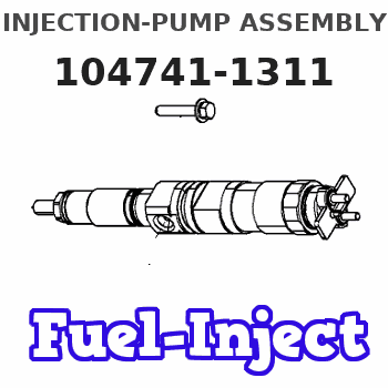
Information injection-pump assembly
ZEXEL
104741-1311
1047411311
ISUZU
8944198522
8944198522
Rating:
Cross reference number
ZEXEL
104741-1311
1047411311
ISUZU
8944198522
8944198522
Zexel num
Bosch num
Firm num
Name
Calibration Data:
Adjustment conditions
Test oil
1404 Test oil ISO4113orSAEJ967d
1404 Test oil ISO4113orSAEJ967d
Test oil temperature
degC
45
45
50
Nozzle
105000-2010
Bosch type code
NP-DN12SD12TT
Nozzle holder
105780-2080
Opening pressure
MPa
14.7
14.7
15.19
Opening pressure
kgf/cm2
150
150
155
Injection pipe
Inside diameter - outside diameter - length (mm) mm 2-6-840
Inside diameter - outside diameter - length (mm) mm 2-6-840
Transfer pump pressure
kPa
20
20
20
Transfer pump pressure
kgf/cm2
0.2
0.2
0.2
Direction of rotation (viewed from drive side)
Left L
Left L
Injection timing adjustment
Pump speed
r/min
1000
1000
1000
Average injection quantity
mm3/st.
40.1
39.6
40.6
Difference in delivery
mm3/st.
3.5
Basic
*
Injection timing adjustment_02
Pump speed
r/min
2250
2250
2250
Average injection quantity
mm3/st.
16.1
12.6
19.6
Injection timing adjustment_03
Pump speed
r/min
2000
2000
2000
Average injection quantity
mm3/st.
40.95
38.4
43.5
Injection timing adjustment_04
Pump speed
r/min
1600
1600
1600
Average injection quantity
mm3/st.
42.95
40.4
45.5
Injection timing adjustment_05
Pump speed
r/min
1000
1000
1000
Average injection quantity
mm3/st.
40.1
39.1
41.1
Injection timing adjustment_06
Pump speed
r/min
700
700
700
Average injection quantity
mm3/st.
34
31.5
36.5
Injection timing adjustment_07
Pump speed
r/min
500
500
500
Average injection quantity
mm3/st.
32.1
28.6
35.6
Injection quantity adjustment
Pump speed
r/min
2250
2250
2250
Average injection quantity
mm3/st.
16.1
13.1
19.1
Difference in delivery
mm3/st.
4.5
Basic
*
Injection quantity adjustment_02
Pump speed
r/min
2350
2350
2350
Average injection quantity
mm3/st.
12.1
Governor adjustment
Pump speed
r/min
385
385
385
Average injection quantity
mm3/st.
7.7
5.7
9.7
Difference in delivery
mm3/st.
2
Basic
*
Governor adjustment_02
Pump speed
r/min
300
300
300
Average injection quantity
mm3/st.
12.5
9.5
15.5
Governor adjustment_03
Pump speed
r/min
385
385
385
Average injection quantity
mm3/st.
7.7
5.7
9.7
Governor adjustment_04
Pump speed
r/min
450
450
450
Average injection quantity
mm3/st.
5
Timer adjustment
Pump speed
r/min
100
100
100
Average injection quantity
mm3/st.
65
65
Basic
*
Speed control lever angle
Pump speed
r/min
385
385
385
Average injection quantity
mm3/st.
0
0
0
Remarks
Magnet OFF
Magnet OFF
0000000901
Pump speed
r/min
1600
1600
1600
Overflow quantity
cm3/min
430
300
560
Stop lever angle
Pump speed
r/min
1600
1600
1600
Pressure
kPa
539.5
520
559
Pressure
kgf/cm2
5.5
5.3
5.7
Basic
*
Stop lever angle_02
Pump speed
r/min
500
500
500
Pressure
kPa
108
108
Pressure
kgf/cm2
1.1
1.1
Stop lever angle_03
Pump speed
r/min
1200
1200
1200
Pressure
kPa
421.5
392
451
Pressure
kgf/cm2
4.3
4
4.6
Stop lever angle_04
Pump speed
r/min
1600
1600
1600
Pressure
kPa
539.5
520
559
Pressure
kgf/cm2
5.5
5.3
5.7
Stop lever angle_05
Pump speed
r/min
2000
2000
2000
Pressure
kPa
666.5
637
696
Pressure
kgf/cm2
6.8
6.5
7.1
0000001101
Pump speed
r/min
1600
1600
1600
Timer stroke
mm
5
4.8
5.2
Basic
*
_02
Pump speed
r/min
1030
1030
1030
Timer stroke
mm
0.5
0.5
0.5
_03
Pump speed
r/min
1200
1200
1200
Timer stroke
mm
1.8
1.3
2.3
_04
Pump speed
r/min
1600
1600
1600
Timer stroke
mm
5
4.7
5.3
_05
Pump speed
r/min
2000
2000
2000
Timer stroke
mm
7.85
7.4
8.3
0000001201
Max. applied voltage
V
8
8
8
Test voltage
V
13
12
14
Timing setting
K dimension
mm
2.8
2.7
2.9
KF dimension
mm
5
4.9
5.1
MS dimension
mm
1
0.9
1.1
Pre-stroke
mm
0.45
0.43
0.47
Control lever angle alpha
deg.
18
14
22
Control lever angle beta
deg.
37
32
42
Information:
Introduction
Do not perform any procedure in this Special Instruction until you read this information and you understand this information.This Special Instruction provides the following information for 3600 Diesel Engines:
Identification of a service tool
A procedure to check cylinder pressureService Tool
Illustration 1 g01250874
4C-6585 Indicator Group (1) Hand tool for tightening gauge connectionProcedure for Checking Cylinder Pressure
Take the readings for cylinder pressure at the rated speed and at the rated load in order to obtain the peak cylinder pressure for a specific rating.Readings for cylinder pressure can also be taken at a light load condition or at a no-load condition. These pressure readings can be used as a baseline for a comparison at a later date. For a valid comparison, pressure measurements that are taken at a later date must duplicate the initial load conditions.
Illustration 2 g01250892
(2) Cylinder pressure valve (Kiene valve) (3) Valve stem (4) Cap
Remove cap (4) from valve (2) .
Fluids may escape from the cylinder pressure valves at high velocity during this procedure and cause personal injury. Always stay clear and keep personnel away from the cylinder pressure valves during this procedure.
Stand to the side of the valve and open valve stem (3) approximately 90° (1/4 turn) counterclockwise. Close valve stem (3). This will blow any foreign debris out of the valve.
Illustration 3 g01250917
(5) 4C-9736 Pressure Gauge (6) 4C-9737 Gauge connection
Install the 4C-6585 Indicator group on the valve. Use tool (1) that is provided in the indicator group in order to tighten gauge connection (6) to a torque of 17 3 N m (12 2 lb ft). Do not overtighten the gauge connection.
Open valve stem (3) by approximately 540° (1 1/2 turn) counterclockwise. Document the reading on pressure gauge (5) and close valve stem (3). Tighten the valve stem to a torque of 24 3 N m (18 2 lb ft). Do not overtighten the valve stem.
Use the hand tool that is provided in the indicator group in order to loosen the gauge connection. Remove the 4C-6585 Indicator Group .
Install cap (4). Tighten to a torque of 17 3 N m (12 2 lb ft). Do not overtighten the cap.