Information injection-pump assembly
ZEXEL
104741-1101
1047411101
ISUZU
8941403872
8941403872

Rating:
Cross reference number
ZEXEL
104741-1101
1047411101
ISUZU
8941403872
8941403872
Zexel num
Bosch num
Firm num
Name
Calibration Data:
Adjustment conditions
Test oil
1404 Test oil ISO4113orSAEJ967d
1404 Test oil ISO4113orSAEJ967d
Test oil temperature
degC
45
45
50
Nozzle
105000-2010
Bosch type code
NP-DN12SD12TT
Nozzle holder
105780-2080
Opening pressure
MPa
14.7
14.7
15.19
Opening pressure
kgf/cm2
150
150
155
Injection pipe
Inside diameter - outside diameter - length (mm) mm 2-6-840
Inside diameter - outside diameter - length (mm) mm 2-6-840
Transfer pump pressure
kPa
20
20
20
Transfer pump pressure
kgf/cm2
0.2
0.2
0.2
Direction of rotation (viewed from drive side)
Left L
Left L
Injection timing adjustment
Pump speed
r/min
1000
1000
1000
Average injection quantity
mm3/st.
44.3
43.8
44.8
Difference in delivery
mm3/st.
3.5
Basic
*
Oil temperature
degC
50
48
52
Injection timing adjustment_02
Pump speed
r/min
500
500
500
Average injection quantity
mm3/st.
44.9
41.4
48.4
Difference in delivery
mm3/st.
5
Oil temperature
degC
48
46
50
Injection timing adjustment_03
Pump speed
r/min
700
700
700
Average injection quantity
mm3/st.
40.4
38.4
42.4
Difference in delivery
mm3/st.
4.5
Oil temperature
degC
50
48
52
Injection timing adjustment_04
Pump speed
r/min
1000
1000
1000
Average injection quantity
mm3/st.
44.3
43.3
45.3
Difference in delivery
mm3/st.
3.5
Basic
*
Oil temperature
degC
50
48
52
Injection timing adjustment_05
Pump speed
r/min
1450
1450
1450
Average injection quantity
mm3/st.
46.9
44.9
48.9
Difference in delivery
mm3/st.
5.5
Oil temperature
degC
50
48
52
Injection timing adjustment_06
Pump speed
r/min
1800
1800
1800
Average injection quantity
mm3/st.
45
42.5
47.5
Difference in delivery
mm3/st.
5
Oil temperature
degC
50
48
52
Injection quantity adjustment
Pump speed
r/min
2100
2100
2100
Average injection quantity
mm3/st.
20.1
17.1
23.1
Difference in delivery
mm3/st.
6
Basic
*
Oil temperature
degC
52
50
54
Injection quantity adjustment_02
Pump speed
r/min
2300
2300
2300
Average injection quantity
mm3/st.
5
Oil temperature
degC
52
50
54
Injection quantity adjustment_03
Pump speed
r/min
2100
2100
2100
Average injection quantity
mm3/st.
20.1
17.1
23.1
Difference in delivery
mm3/st.
6
Oil temperature
degC
52
50
54
Governor adjustment
Pump speed
r/min
390
390
390
Average injection quantity
mm3/st.
8
6
10
Difference in delivery
mm3/st.
2
Basic
*
Oil temperature
degC
48
46
50
Governor adjustment_02
Pump speed
r/min
390
390
390
Average injection quantity
mm3/st.
8
6
10
Difference in delivery
mm3/st.
2
Oil temperature
degC
48
46
50
Timer adjustment
Pump speed
r/min
100
100
100
Average injection quantity
mm3/st.
75
75
115
Basic
*
Oil temperature
degC
48
46
50
Remarks
Full
Full
Timer adjustment_02
Pump speed
r/min
100
100
100
Average injection quantity
mm3/st.
95
75
115
Oil temperature
degC
48
46
50
Speed control lever angle
Pump speed
r/min
390
390
390
Average injection quantity
mm3/st.
0
0
0
Oil temperature
degC
48
46
50
Remarks
Magnet OFF at idling position
Magnet OFF at idling position
0000000901
Pump speed
r/min
1450
1450
1450
Overflow quantity
cm3/min
510
380
640
Oil temperature
degC
50
48
52
Remarks
OFF
OFF
Stop lever angle
Pump speed
r/min
1450
1450
1450
Pressure with S/T OFF
kPa
510
490
530
Pressure with S/T OFF
kgf/cm2
5.2
5
5.4
Basic
*
Oil temperature
degC
50
48
52
Remarks
OFF
OFF
Stop lever angle_02
Pump speed
r/min
1450
1450
1450
Pressure with S/T OFF
kPa
510
490
530
Pressure with S/T OFF
kgf/cm2
5.2
5
5.4
Basic
*
Oil temperature
degC
50
48
52
Stop lever angle_03
Pump speed
r/min
1950
1950
1950
Pressure with S/T OFF
kPa
657
628
686
Pressure with S/T OFF
kgf/cm2
6.7
6.4
7
Oil temperature
degC
50
48
52
0000001101
Pump speed
r/min
1450
1450
1450
Timer stroke with S/T OFF
mm
1.9
1.7
2.1
Basic
*
Oil temperature
degC
50
48
52
Remarks
OFF
OFF
_02
Pump speed
r/min
560
560
560
Timer stroke with S/T ON
mm
0.5
0.5
0.5
Oil temperature
degC
50
48
52
_03
Pump speed
r/min
1270
1270
1270
Timer stroke with S/T OFF
mm
0.5
0.5
0.5
Oil temperature
degC
50
48
52
_04
Pump speed
r/min
1450
1450
1450
Timer stroke with S/T OFF
mm
1.9
1.7
2.1
Basic
*
Oil temperature
degC
50
48
52
_05
Pump speed
r/min
1950
1950
1950
Timer stroke with S/T OFF
mm
5.7
5.4
6.1
Oil temperature
degC
50
48
52
0000001201
Max. applied voltage
V
8
8
8
Test voltage
V
13
12
14
0000001501
Pump speed
r/min
1000
1000
1000
Height
m
2000
2000
2000
Atmospheric pressure difference
kPa
-21.9
-21.9
-21.9
Atmospheric pressure difference
mmHg
-164
-164
-164
Average injection quantity
mm3/st.
39.5
39.5
39.5
Decrease qty
mm3/st.
4.7
3.7
5.7
Decrease rate
%
11
8
14
Basic
*
Oil temperature
degC
50
48
52
_02
Pump speed
r/min
1000
1000
1000
Height
m
0
0
0
Atmospheric pressure difference
kPa
0
0
0
Atmospheric pressure difference
mmHg
0
0
0
Decrease qty
mm3/st.
0
0
0
Decrease rate
%
0
0
0
Oil temperature
degC
50
48
52
_03
Pump speed
r/min
1000
1000
1000
Height
m
500
500
500
Atmospheric pressure difference
kPa
-5.9
-9.2
-2.6
Atmospheric pressure difference
mmHg
-44
-46.5
-41.5
Oil temperature
degC
50
48
52
Remarks
Point of inflection
Point of inflection
_04
Pump speed
r/min
1000
1000
1000
Height
m
2000
2000
2000
Atmospheric pressure difference
kPa
-21.9
-21.9
-21.9
Atmospheric pressure difference
mmHg
-164
-164
-164
Decrease qty
mm3/st.
-4.7
-5.7
-3.7
Decrease rate
%
-11
-14
-8
Oil temperature
degC
50
48
52
Timing setting
K dimension
mm
2.8
2.7
2.9
KF dimension
mm
5
4.9
5.1
MS dimension
mm
1
0.9
1.1
Pre-stroke
mm
0.45
0.43
0.47
Control lever angle alpha
deg.
18
14
22
Control lever angle beta
deg.
35
30
40
Test data Ex:
0000001501 ANEROID COMPENSATOR
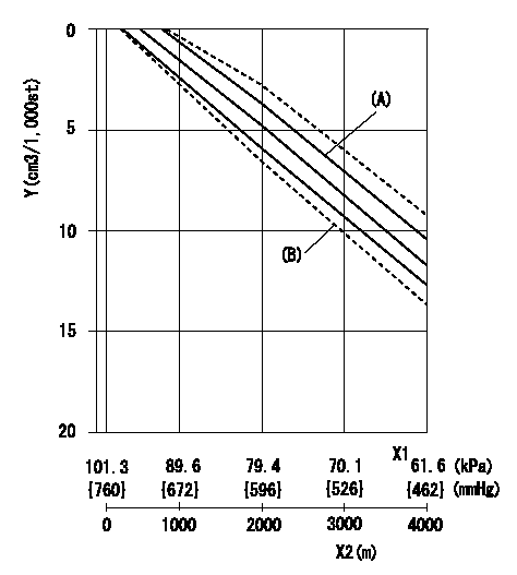
ACS adjustment
Full load injection quantity at high altitudes and ACS adjusting method
1. Full load injection quantity adjustment
(1)Remove the ACS cover and remove the bellows and adjusting shim.
(2)Perform all adjustments as per the adjustment standard except for ACS adjustment.
2. ACS adjustment
(1)Assemble the ACS cover, bellows and adjusting shim.
(2)At pump speed N1, adjust using a shim to obtain the decrease for the altitude shown in the table.
X1 = atmospheric pressure
X2 = altitude
Y = decrease quantity
(A) = adjustment value
(B) = test value
----------
N1=1000r/min
----------
----------
N1=1000r/min
----------
Information:
Table 1
Sales Model Adaptable to Machines Effective in Production with Machines
D3K 2 S/N:JPJ1-199 S/N:JPJ200-UP
S/N:KL21-208 S/N:KL2209-UP
S/N:LT31-113 S/N:LT3114-UP
S/N:FT31-102 S/N:FT3103-UP
S/N:KF21-174 S/N:KF2175-UP
D4K 2 S/N:KR21-203 S/N:KR2204-UP
S/N:RT31-130 S/N:RT3131-UP
S/N:KM21-196 S/N:KM2197-UP
S/N:MT31-119 S/N:MT3120-UP
D5K 2 S/N:KY21-357 S/N:KY2358-UP
S/N:RRE1-232 S/N:RRE233-UP
S/N:YT31-153 S/N:YT3154-UP
S/N:KW21-308 S/N:KW2309-UP
S/N:WT31-145 S/N:WT3146-UP In the event, the original bolt should come loose or is lost, use one of the following procedures and parts list for reworking the latch assembly.Rework Procedure
Table 2
New Parts List
Item Quantity Part Number Description
1 1 275-0571 Latch Cam
2 1 7X-2619 Bolt
3 1 9X-8256 Washer
4 1 275-0572 Latch As
Illustration 1 g06026857Procedure if the original cam latch retaining bolt is loose
Illustration 2 g06025999
Remove bolt (2), keeping cam latch (1) in position.
Apply Loctite 243 to the threads of bolt (2). Torque the bolt to 6 1 N m (53 9 lb in) using a torque wrench.Procedure if only the original cam latch bolt and cam latch are missing
Illustration 3 g06026021
Install new cam latch (1) to the latch body.
Replace missing retaining bolt with a 7X-2619 Bolt (2) and 9X-8256 Washer (3). This washer is required as the new bolt is too long and will bottom out in the latch body before tightening. Install using Loctite 243. Torque the bolt to 6 1 N m (53 9 lb in) using a torque wrench.Procedure if the original cam latch retaining bolt, cam latch and latch assembly are missing
Illustration 4 g06026825
Illustration 5 g06026826
Illustration 6 g06026831
(E) Side 1 of Retaining Nut
(F) Side 2 of Retaining Nut
Install new latch housing (A), with non-metallic washer (on outside of door) and Latch body/ handle (4) in door.Note: Orient two surfaces (C)and handle as shown in Illustration 5. Lock indicator on outside of handle is at the top.
Secure housing with retaining nut (B) and torque to 15 3 N m (11 2 lb ft), using a torque wrench.Note: During assembly, use four nubs (D) on Side (E) of nut against door.
Remove original bolt (C).
Install latch cam (1).
Apply Loctite 243 to the threads on the original bolt (C). Torque the bolt to 6 1 N m (53 9 lb in).Note: Use torque wrench for tightening.