Information injection-pump assembly
ZEXEL
104741-1030
1047411030
ISUZU
8941531940
8941531940

Rating:
Cross reference number
ZEXEL
104741-1030
1047411030
ISUZU
8941531940
8941531940
Zexel num
Bosch num
Firm num
Name
Calibration Data:
Adjustment conditions
Test oil
1404 Test oil ISO4113orSAEJ967d
1404 Test oil ISO4113orSAEJ967d
Test oil temperature
degC
45
45
50
Nozzle
105000-2010
Bosch type code
NP-DN12SD12TT
Nozzle holder
105780-2080
Opening pressure
MPa
14.7
14.7
15.19
Opening pressure
kgf/cm2
150
150
155
Injection pipe
Inside diameter - outside diameter - length (mm) mm 2-6-840
Inside diameter - outside diameter - length (mm) mm 2-6-840
Transfer pump pressure
kPa
20
20
20
Transfer pump pressure
kgf/cm2
0.2
0.2
0.2
Direction of rotation (viewed from drive side)
Right R
Right R
(Solenoid timer adjustment condition)
OFF
Timer measuring device installation position
Low pressure side LOW PRESSURE SIDE
Low pressure side LOW PRESSURE SIDE
Injection timing adjustment
Pump speed
r/min
1000
1000
1000
Average injection quantity
mm3/st.
44.6
44.1
45.1
Difference in delivery
mm3/st.
3.5
Basic
*
Injection timing adjustment_02
Pump speed
r/min
2100
2100
2100
Average injection quantity
mm3/st.
12.8
9.3
16.3
Injection timing adjustment_03
Pump speed
r/min
1700
1700
1700
Average injection quantity
mm3/st.
47.3
44.8
49.8
Injection timing adjustment_04
Pump speed
r/min
1350
1350
1350
Average injection quantity
mm3/st.
47.5
45.5
49.5
Injection timing adjustment_05
Pump speed
r/min
1000
1000
1000
Average injection quantity
mm3/st.
44.6
43.6
45.6
Injection timing adjustment_06
Pump speed
r/min
700
700
700
Average injection quantity
mm3/st.
36.6
34.6
38.6
Injection quantity adjustment
Pump speed
r/min
2100
2100
2100
Average injection quantity
mm3/st.
12.7
9.6
15.8
Difference in delivery
mm3/st.
3.5
Basic
*
Injection quantity adjustment_02
Pump speed
r/min
2300
2300
2300
Average injection quantity
mm3/st.
7
Governor adjustment
Pump speed
r/min
390
390
390
Average injection quantity
mm3/st.
9
7
11
Difference in delivery
mm3/st.
2
Basic
*
Governor adjustment_02
Pump speed
r/min
390
390
390
Average injection quantity
mm3/st.
9
7
11
Governor adjustment_03
Pump speed
r/min
550
550
550
Average injection quantity
mm3/st.
3
Timer adjustment
Pump speed
r/min
100
100
100
Average injection quantity
mm3/st.
95
75
115
Basic
*
Speed control lever angle
Pump speed
r/min
390
390
390
Average injection quantity
mm3/st.
0
0
0
Remarks
Magnet OFF
Magnet OFF
0000000901
Pump speed
r/min
1550
1550
1550
Overflow quantity with S/T OFF
cm3/min
531
402
660
Stop lever angle
Pump speed
r/min
1550
1550
1550
Pressure
kPa
519.5
500
539
Pressure
kgf/cm2
5.3
5.1
5.5
Basic
*
Stop lever angle_02
Pump speed
r/min
1000
1000
1000
Pressure
kPa
313.5
284
343
Pressure
kgf/cm2
3.2
2.9
3.5
Stop lever angle_03
Pump speed
r/min
1550
1550
1550
Pressure
kPa
519.5
500
539
Pressure
kgf/cm2
5.3
5.1
5.5
Stop lever angle_04
Pump speed
r/min
1850
1850
1850
Pressure
kPa
617.5
588
647
Pressure
kgf/cm2
6.3
6
6.6
0000001101
Pump speed
r/min
1550
1550
1550
Timer stroke
mm
1.9
1.7
2.1
Basic
*
_02
Pump speed
r/min
730
630
830
Timer stroke with S/T ON
mm
0.5
0.5
0.5
_03
Pump speed
r/min
1440
1390
1490
Timer stroke with S/T OFF
mm
0.5
0.5
0.5
_04
Pump speed
r/min
1550
1550
1550
Timer stroke with S/T OFF
mm
1.9
1.6
2.2
_05
Pump speed
r/min
1850
1850
1850
Timer stroke with S/T OFF
mm
5.7
5.3
6.1
0000001201
Max. applied voltage
V
8
8
8
Test voltage
V
13
12
14
Timing setting
K dimension
mm
2.8
2.7
2.9
KF dimension
mm
5
4.9
5.1
MS dimension
mm
1
0.9
1.1
Pre-stroke
mm
0.45
0.43
0.47
Control lever angle alpha
deg.
18
14
22
Control lever angle beta
deg.
35
30
40
Test data Ex:
0000001801 TIMER STROKE
Timer adjustment
Assemble the timer's measuring device on the low pressure side and measure timer advance.
Select one of the 6 timer springs. It is necessary to install at least 1 shim (0.6 mm) on either side.
Maximum is L1 mm on piston side and L2 mm on cover side. Do not exceed.
Use pipe corresponding to 146606-3920.
----------
L1=3mm L2=3.8mm
----------
----------
L1=3mm L2=3.8mm
----------
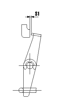
0000001901 V-FICD ADJUSTMENT

Adjustment of the V-FICD
1. Adjust the actuator rod to obtain S1.
2. Apply negative pressure P1 to the actuator and confirm the full stroke.
----------
S1=1+1mm P1=-53.3kPa(-400mmHg)
----------
S1=1+1mm
----------
S1=1+1mm P1=-53.3kPa(-400mmHg)
----------
S1=1+1mm
Information:
Do not use single grade API CF oils or multigrade API CF oils in Cat 3500 Series, C175 Series, and smaller Direct Injection (DI) diesel engines.API CF oils are only recommended for Cat 3600 Series and C280 Series diesel engines, and Cat engines that have precombustion chamber (PC) fuel systems. Oils that are used in Cat 3600 Series and C280 Series diesel engines must also pass a 7000 hour field performance evaluation. Contact your Cat dealer for details.
Fuel Sulfur Impact on Engine Oil
Follow the recommendations given in the "Fuel Sulfur Impact on Engine Oil" section given earlier in this Special Publication in the Engine Oil chapter.Use the oils recommended for the precombustion chamber engines in order to ensure the protection of the engines and follow the recommendations in your Operation and Maintenance Manual for oil drain intervals.
Depending on application severity and localized environmental conditions, and also depending on maintenance practices, operating Direct Injection (DI) diesel engines and operating PC (Precombustion Chamber) diesel engines on fuel with sulfur levels over 0.1 percent (1000 ppm) may require shortened oil change intervals to help maintain adequate wear protection. Refer to this Special Publication, “Fuel Specifications” section, “Diesel Fuel Sulfur” topic for additional information.
Note: For PC (Precombustion Chamber) diesel engines, which are mainly 1990 and older engines, the minimum new oil TBN must be 20 times the fuel sulfur level. The diesel engine oil types, specifications, and viscosity grades recommendations provided for DI diesel engines in this Special Publication are also applicable to PC diesel engines.Consult with your Cat dealer regarding the testing that is required in establishing oil drain intervals that are optimized for your application.