Information injection-pump assembly
ZEXEL
104741-1010
1047411010
ISUZU
8941532800
8941532800

Rating:
Cross reference number
ZEXEL
104741-1010
1047411010
ISUZU
8941532800
8941532800
Zexel num
Bosch num
Firm num
Name
Calibration Data:
Adjustment conditions
Test oil
1404 Test oil ISO4113orSAEJ967d
1404 Test oil ISO4113orSAEJ967d
Test oil temperature
degC
45
45
50
Nozzle
105000-2010
Bosch type code
NP-DN12SD12TT
Nozzle holder
105780-2080
Opening pressure
MPa
14.7
14.7
15.19
Opening pressure
kgf/cm2
150
150
155
Injection pipe
Inside diameter - outside diameter - length (mm) mm 2-6-840
Inside diameter - outside diameter - length (mm) mm 2-6-840
Transfer pump pressure
kPa
20
20
20
Transfer pump pressure
kgf/cm2
0.2
0.2
0.2
Direction of rotation (viewed from drive side)
Right R
Right R
(Solenoid timer adjustment condition)
OFF
Timer measuring device installation position
Low pressure side LOW PRESSURE SIDE
Low pressure side LOW PRESSURE SIDE
Injection timing adjustment
Pump speed
r/min
1000
1000
1000
Average injection quantity
mm3/st.
47.5
47
48
Difference in delivery
mm3/st.
4
Basic
*
Injection timing adjustment_02
Pump speed
r/min
2100
2100
2100
Average injection quantity
mm3/st.
13.1
9.6
16.6
Injection timing adjustment_03
Pump speed
r/min
1800
1800
1800
Average injection quantity
mm3/st.
47.4
44.9
49.9
Injection timing adjustment_04
Pump speed
r/min
1450
1450
1450
Average injection quantity
mm3/st.
48.4
46.4
50.4
Injection timing adjustment_05
Pump speed
r/min
1000
1000
1000
Average injection quantity
mm3/st.
47.5
46.5
48.5
Injection timing adjustment_06
Pump speed
r/min
700
700
700
Average injection quantity
mm3/st.
42.4
40.4
44.4
Injection quantity adjustment
Pump speed
r/min
2100
2100
2100
Average injection quantity
mm3/st.
13.1
10.1
16.1
Difference in delivery
mm3/st.
4
Basic
*
Injection quantity adjustment_02
Pump speed
r/min
2300
2300
2300
Average injection quantity
mm3/st.
5
Governor adjustment
Pump speed
r/min
390
390
390
Average injection quantity
mm3/st.
8
6
10
Difference in delivery
mm3/st.
2
Basic
*
Governor adjustment_02
Pump speed
r/min
390
390
390
Average injection quantity
mm3/st.
8
6
10
Governor adjustment_03
Pump speed
r/min
550
550
550
Average injection quantity
mm3/st.
3
Timer adjustment
Pump speed
r/min
100
100
100
Average injection quantity
mm3/st.
95
75
115
Basic
*
Speed control lever angle
Pump speed
r/min
390
390
390
Average injection quantity
mm3/st.
0
0
0
Remarks
Magnet OFF
Magnet OFF
0000000901
Pump speed
r/min
1600
1600
1600
Overflow quantity with S/T OFF
cm3/min
531
402
660
Stop lever angle
Pump speed
r/min
1600
1600
1600
Pressure
kPa
539.5
520
559
Pressure
kgf/cm2
5.5
5.3
5.7
Basic
*
Stop lever angle_02
Pump speed
r/min
1000
1000
1000
Pressure
kPa
313.5
284
343
Pressure
kgf/cm2
3.2
2.9
3.5
Stop lever angle_03
Pump speed
r/min
1600
1600
1600
Pressure
kPa
539.5
520
559
Pressure
kgf/cm2
5.5
5.3
5.7
Stop lever angle_04
Pump speed
r/min
1900
1900
1900
Pressure
kPa
627.5
598
657
Pressure
kgf/cm2
6.4
6.1
6.7
0000001101
Pump speed
r/min
1600
1600
1600
Timer stroke
mm
1.9
1.7
2.1
Basic
*
_02
Pump speed
r/min
790
690
890
Timer stroke with S/T ON
mm
0.5
0.5
0.5
_03
Pump speed
r/min
1490
1440
1540
Timer stroke with S/T OFF
mm
0.5
0.5
0.5
_04
Pump speed
r/min
1600
1600
1600
Timer stroke with S/T OFF
mm
1.9
1.6
2.2
_05
Pump speed
r/min
1900
1900
1900
Timer stroke with S/T OFF
mm
5.7
5.3
6.1
0000001201
Max. applied voltage
V
8
8
8
Test voltage
V
13
12
14
Timing setting
K dimension
mm
2.8
2.7
2.9
KF dimension
mm
5
4.9
5.1
MS dimension
mm
1
0.9
1.1
Pre-stroke
mm
0.45
0.43
0.47
Control lever angle alpha
deg.
18
14
22
Control lever angle beta
deg.
35
30
40
Test data Ex:
0000001801 V-FICD ADJUSTMENT

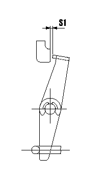
Adjustment of the V-FICD
1. Adjust the actuator rod to obtain S1.
2. Apply negative pressure P1 to the actuator and confirm the full stroke.
----------
S1=1+1mm P1=-53.3kPa(-400mmHg)
----------
S1=1+1mm
----------
S1=1+1mm P1=-53.3kPa(-400mmHg)
----------
S1=1+1mm
0000001901 TIMER STROKE
Timer adjustment
Assemble the timer's measuring device on the low pressure side and measure timer advance.
Select one of the 6 timer springs. It is necessary to install at least 1 shim (0.6 mm) on either side.
Maximum is L1 mm on piston side and L2 mm on cover side. Do not exceed.
Use pipe corresponding to 146606-3920.
----------
L1=3mm L2=3.8mm
----------
----------
L1=3mm L2=3.8mm
----------
Information:
Not following the recommendations found in this Special Publication can lead to reduced performance and compartment failure.
Cat Fluids
Cat fluids have been developed and tested by Caterpillar in order to increase the performance of Cat components and the life of Cat components. The quality of finished oil is dependent on the quality of the base stock, the quality of the additives and the compatibility of the base stock and additives. Cat fluids are formulated of high quality refined oil base stocks and additives of optimal chemistry and quantity to provide high performance in engines and machine components. Cat fluids are used for factory fill of Cat engines and components and are offered by Caterpillar dealers for service fills and as aftermarket products. Consult your Caterpillar dealer for more information on these Cat fluids.
Table 1
Cat lubricants for on-highway applications
Compartment or System Oil Type Oil Viscosity Grade Typical Application Temp C (1) Typical Application Temp F (1)
Min Max Min Max
Engine Oils Cat DEO-ULS SAE 15W-40 -9.5 50 15 122
SAE 10W-30 -18 40 0 104
Cat DEO-ULS SYN SAE 5W-40 -30 50 -22 122
Cat DEO SAE 15W-40 -9.5 50 15 122
SAE 10W-30 -18 40 0 104
Cat DEO SYN SAE 5W-40 -30 50 -22 122
Cat Arctic DEO SYN SAE 0W-30 -40 30 -40 86
Transmission and Drive Train Oils (On-Highway applications) Cat ATF-HD Multi-Grade Synthetic (2) (2)
Hydraulic Oils Cat HYDO Advanced SAE 10W -20 40 -4 104
SAE 30 10 50 50 122
Cat Bio HYDO (HEES) ISO 46 Multi-grade -25 45 -13 113
( 1 ) The application temperatures will vary per machine application. Follow the recommendations provided in the "Lubricant Viscosity" section of this Special Publication and your Operation and Maintenance Manual for fluid temperature recommendations of the specific application and machine compartment.
( 2 ) If the temperature is less than -23° C (-10° F), warm up the engine for 20 minutes. As an alternative to the warm up, you may install an appropriate transmission oil heater.
Table 2
Caterpillar Grease and Coolant products
Grease Cat Multipurpose Grease
Cat Advanced 3Moly Grease
Cat Ultra 5Moly Grease
Cat Desert Gold Grease
Cat Arctic Platinum Grease
Cat High Speed Ball Bearing Grease
Cat White Assembly Grease
Coolants Cat ELC (Extended Life Coolant)
Cat ELC Extender (for use with Cat ELC)
Cat DEAC (Diesel Engine Antifreeze/Coolant)
Cat SCA (Supplemental Coolant Additive, for use with Cat DEAC) This information is only for Caterpillar on-highway diesel engines. For more lubricant recommendations see the following Special Publications:
Special Publication, SEBU6251, "Caterpillar Commercial Diesel Engine Fluid Recommendations"
Special Publication, SEBU6250, "Caterpillar Machine Fluids Recommendations"
Special Publication,