Information injection-pump assembly
ZEXEL
104740-9970
1047409970
NISSAN-DIESEL
1670030N01
1670030n01
Rating:
Cross reference number
ZEXEL
104740-9970
1047409970
NISSAN-DIESEL
1670030N01
1670030n01
Zexel num
Bosch num
Firm num
Name
Calibration Data:
Adjustment conditions
Test oil
1404 Test oil ISO4113orSAEJ967d
1404 Test oil ISO4113orSAEJ967d
Test oil temperature
degC
45
45
50
Nozzle
105000-2010
Bosch type code
NP-DN12SD12TT
Nozzle holder
105780-2080
Opening pressure
MPa
14.7
14.7
15.19
Opening pressure
kgf/cm2
150
150
155
Injection pipe
Inside diameter - outside diameter - length (mm) mm 2-6-840
Inside diameter - outside diameter - length (mm) mm 2-6-840
Transfer pump pressure
kPa
20
20
20
Transfer pump pressure
kgf/cm2
0.2
0.2
0.2
Direction of rotation (viewed from drive side)
Right R
Right R
(Solenoid timer adjustment condition)
OFF
Injection timing adjustment
Pump speed
r/min
1100
1100
1100
Average injection quantity
mm3/st.
44.6
44.1
45.1
Difference in delivery
mm3/st.
3
Basic
*
Injection timing adjustment_02
Pump speed
r/min
2550
2550
2550
Average injection quantity
mm3/st.
8.9
5.4
12.4
Injection timing adjustment_03
Pump speed
r/min
2350
2350
2350
Average injection quantity
mm3/st.
30.3
27.8
32.8
Injection timing adjustment_04
Pump speed
r/min
2150
2150
2150
Average injection quantity
mm3/st.
38
35.9
40.1
Injection timing adjustment_05
Pump speed
r/min
1100
1100
1100
Average injection quantity
mm3/st.
44.6
43.6
45.6
Injection timing adjustment_06
Pump speed
r/min
600
600
600
Average injection quantity
mm3/st.
43.5
41.5
45.5
Injection quantity adjustment
Pump speed
r/min
2350
2350
2350
Average injection quantity
mm3/st.
30.3
28.3
32.3
Basic
*
Injection quantity adjustment_02
Pump speed
r/min
2700
2700
2700
Average injection quantity
mm3/st.
5
Governor adjustment
Pump speed
r/min
350
350
350
Average injection quantity
mm3/st.
6.5
4.5
8.5
Difference in delivery
mm3/st.
2
Basic
*
Governor adjustment_02
Pump speed
r/min
350
350
350
Average injection quantity
mm3/st.
6.5
4.5
8.5
Governor adjustment_03
Pump speed
r/min
400
400
400
Average injection quantity
mm3/st.
3
Timer adjustment
Pump speed
r/min
100
100
100
Average injection quantity
mm3/st.
62.5
45
80
Basic
*
Speed control lever angle
Pump speed
r/min
350
350
350
Average injection quantity
mm3/st.
0
0
0
Remarks
Magnet OFF
Magnet OFF
0000000901
Pump speed
r/min
1100
1100
1100
Overflow quantity
cm3/min
390
258
522
_02
Pump speed
r/min
1100
1100
1100
Overflow quantity
cm3/min
489
360
618
Remarks
Without an O-ring
Without an O-ring
Stop lever angle
Pump speed
r/min
1100
1100
1100
Pressure with S/T ON
kPa
480.5
441
520
Pressure with S/T ON
kgf/cm2
4.9
4.5
5.3
Pressure with S/T OFF
kPa
372.5
343
402
Pressure with S/T OFF
kgf/cm2
3.8
3.5
4.1
Basic
*
Stop lever angle_02
Pump speed
r/min
1100
1100
1100
Pressure with S/T ON
kPa
480.5
441
520
Pressure with S/T ON
kgf/cm2
4.9
4.5
5.3
Pressure with S/T OFF
kPa
372.5
343
402
Pressure with S/T OFF
kgf/cm2
3.8
3.5
4.1
Stop lever angle_03
Pump speed
r/min
1700
1700
1700
Pressure with S/T OFF
kPa
510
481
539
Pressure with S/T OFF
kgf/cm2
5.2
4.9
5.5
Stop lever angle_04
Pump speed
r/min
2150
2150
2150
Pressure with S/T OFF
kPa
598.5
569
628
Pressure with S/T OFF
kgf/cm2
6.1
5.8
6.4
0000001101
Pump speed
r/min
1100
1100
1100
Timer stroke with S/T ON
mm
4.2
3.8
4.6
Timer stroke with S/T OFF
mm
2.5
2.3
2.7
Basic
*
_02
Pump speed
r/min
1100
1100
1100
Timer stroke with S/T ON
mm
4.2
3.7
4.7
Timer stroke with S/T OFF
mm
2.5
2.2
2.8
_03
Pump speed
r/min
1700
1700
1700
Timer stroke with S/T OFF
mm
4.6
4
5.2
_04
Pump speed
r/min
2550
2550
2550
Timer stroke with S/T OFF
mm
7
6.6
7.4
0000001201
Max. applied voltage
V
8
8
8
Test voltage
V
13
12
14
Timing setting
K dimension
mm
3.3
3.2
3.4
KF dimension
mm
5.8
5.7
5.9
MS dimension
mm
1
0.9
1.1
Control lever angle alpha
deg.
54
50
58
Control lever angle beta
deg.
36
31
41
Test data Ex:
0000001801 CONTROL LEVER ANGLE
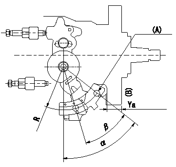
Control lever angle measurement
1. Measure dimension L between the end of the lever and the flange face.
2. Measure the lever angle from the pin hole R (plate).
(A) = lever angle measuring position
(B) = flange face
----------
L=10.7~14.2mm R=49mm
----------
L=10.7~14.2mm R=49mm
----------
L=10.7~14.2mm R=49mm
----------
L=10.7~14.2mm R=49mm
0000001901 ACCELERATOR SWITCH ADJ
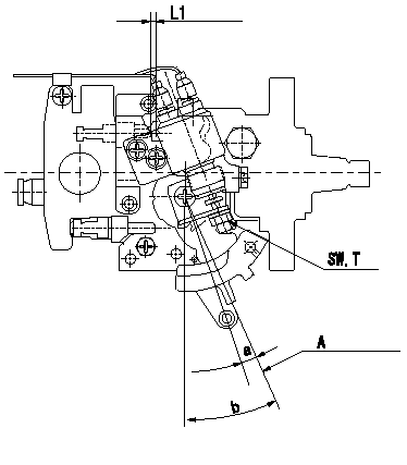
Adjustment of the accelerator switch
ON - OFF changeover point: from idle to c (shim thickness L1 mm)
Idle-d: ON
e-full: OFF
A = idle lever position
----------
c=5+-2deg d=5deg e=5deg L1=3.3+-0.13mm
----------
SW=SW10 T=6~9N-m(0.6~0.9Kgf-m) a=5+-2deg b=25+-2deg L1=3.3mm
----------
c=5+-2deg d=5deg e=5deg L1=3.3+-0.13mm
----------
SW=SW10 T=6~9N-m(0.6~0.9Kgf-m) a=5+-2deg b=25+-2deg L1=3.3mm
Information:
Batteries
Install batteries that will provide adequate cold cranking amps (CCA) in order to start the engine and operate the engine at the coldest expected temperatures. Maintain proper battery electrolyte level. Keep all batteries fully charged to a corrected specific gravity of 1.250 or above and keep the batteries warm. Heating of the battery compartment or storage in a warm location will maximize the cranking power of the battery. The temperature of the batteries has a considerable effect on the available power. The batteries will not have enough power for cranking the engine and starting the engine if the batteries are too cold, even with a warm engine. Batteries typically have only fifty percent of the capability at −10 °C (14 °F) versus 27 °C (81 °F). Only ten percent of the original power is available at a temperature of −35 °C (−31 °F). Check the condition of the batteries and the electrolyte level in each battery cell except for maintenance free batteries. Remove the battery filler caps. Maintain the electrolyte level to the bottom of the openings for the battery filler caps with distilled water. If distilled water is not available, use clean water, that is low in minerals. Do not use artificially softened water or drinking water. The salt in artificially softened water will damage the efficiency of your batteries. At the proper charging rate in a moderate climate, a battery should not require more than 30 cc (1 oz) of water per cell per week. Check the cells weekly in arctic temperatures. The cell water usage could be higher.Block Heaters
A cylinder block coolant heater can improve the startability and a cylinder block coolant heater can reduce the warm-up time by heating the coolant that surrounds the combustion chambers. A cylinder block coolant heater that is powered by electricity can be activated immediately after the engine is stopped. A cylinder block coolant heater will reduce the temperature that will require ether for starting the engine. An effective block heater is a 1250 watt to 1500 watt unit. Contact your truck dealer for more information.Air Inlet Heaters and Ether Starting Systems
If equipped with an air inlet heater (AIH) for cold weather starting, do not use types of starting aids such as ether. Such use could result in an explosion and injury.
When starting the engine with ether, follow these starting procedure instructions carefully. Use ether sparingly and spray it ONLY WHILE CRANKING THE ENGINE. Excessive ether use can cause piston and ring damage. Ether should be used only for cold weather starting.
As temperatures drop below 0 °C (32 °F), starting a cold engine may require assistance in the form of ether starting aids or air inlet heaters. An automatic metered ether injection system is preferred over a manual system. An automatic system reduces the risk of engine damage by minimizing the operator's responsibility in order to correctly determine the quantity of ether that is required. Excessive ether will damage the engine and excessive ether will void the manufacturer's