Information injection-pump assembly
ZEXEL
104740-9910
1047409910
NISSAN-DIESEL
1670022T03
1670022t03

Rating:
Cross reference number
ZEXEL
104740-9910
1047409910
NISSAN-DIESEL
1670022T03
1670022t03
Zexel num
Bosch num
Firm num
Name
Calibration Data:
Adjustment conditions
Test oil
1404 Test oil ISO4113orSAEJ967d
1404 Test oil ISO4113orSAEJ967d
Test oil temperature
degC
45
45
50
Nozzle
105000-2010
Bosch type code
NP-DN12SD12TT
Nozzle holder
105780-2080
Opening pressure
MPa
14.7
14.7
15.19
Opening pressure
kgf/cm2
150
150
155
Injection pipe
Inside diameter - outside diameter - length (mm) mm 2-6-840
Inside diameter - outside diameter - length (mm) mm 2-6-840
Transfer pump pressure
kPa
20
20
20
Transfer pump pressure
kgf/cm2
0.2
0.2
0.2
Direction of rotation (viewed from drive side)
Right R
Right R
(Solenoid timer adjustment condition)
OFF
Injection timing adjustment
Pump speed
r/min
1100
1100
1100
Average injection quantity
mm3/st.
52.3
51.8
52.8
Difference in delivery
mm3/st.
3
Basic
*
Injection timing adjustment_02
Pump speed
r/min
2550
2550
2550
Average injection quantity
mm3/st.
10.1
5.6
14.6
Injection timing adjustment_03
Pump speed
r/min
2350
2350
2350
Average injection quantity
mm3/st.
34.2
31.7
36.7
Injection timing adjustment_04
Pump speed
r/min
2150
2150
2150
Average injection quantity
mm3/st.
42.9
40.8
45
Injection timing adjustment_05
Pump speed
r/min
1100
1100
1100
Average injection quantity
mm3/st.
52.3
51.3
53.3
Injection timing adjustment_06
Pump speed
r/min
600
600
600
Average injection quantity
mm3/st.
52.8
50.8
54.8
Injection quantity adjustment
Pump speed
r/min
2350
2350
2350
Average injection quantity
mm3/st.
34.2
32.2
36.2
Basic
*
Injection quantity adjustment_02
Pump speed
r/min
2700
2700
2700
Average injection quantity
mm3/st.
5
Governor adjustment
Pump speed
r/min
350
350
350
Average injection quantity
mm3/st.
7.3
5.3
9.3
Difference in delivery
mm3/st.
2
Basic
*
Governor adjustment_02
Pump speed
r/min
450
450
450
Average injection quantity
mm3/st.
3
Governor adjustment_03
Pump speed
r/min
350
350
350
Average injection quantity
mm3/st.
7.3
5.3
9.3
Timer adjustment
Pump speed
r/min
100
100
100
Average injection quantity
mm3/st.
62.5
45
80
Basic
*
Speed control lever angle
Pump speed
r/min
350
350
350
Average injection quantity
mm3/st.
0
0
0
Remarks
Magnet OFF
Magnet OFF
0000000901
Pump speed
r/min
1100
1100
1100
Overflow quantity with S/T ON
cm3/min
390
258
522
_02
Pump speed
r/min
1100
1100
1100
Overflow quantity with S/T ON
cm3/min
489
360
618
Remarks
Without an O-ring
Without an O-ring
Stop lever angle
Pump speed
r/min
1100
1100
1100
Pressure with S/T ON
kPa
480.5
441
520
Pressure with S/T ON
kgf/cm2
4.9
4.5
5.3
Pressure with S/T OFF
kPa
372.5
343
402
Pressure with S/T OFF
kgf/cm2
3.8
3.5
4.1
Basic
*
Stop lever angle_02
Pump speed
r/min
1100
1100
1100
Pressure with S/T ON
kPa
480.5
441
520
Pressure with S/T ON
kgf/cm2
4.9
4.5
5.3
Pressure with S/T OFF
kPa
372.5
343
402
Pressure with S/T OFF
kgf/cm2
3.8
3.5
4.1
Stop lever angle_03
Pump speed
r/min
1700
1700
1700
Pressure with S/T ON
kPa
618
579
657
Pressure with S/T ON
kgf/cm2
6.3
5.9
6.7
Pressure with S/T OFF
kPa
510
481
539
Pressure with S/T OFF
kgf/cm2
5.2
4.9
5.5
Stop lever angle_04
Pump speed
r/min
2150
2150
2150
Pressure with S/T OFF
kPa
598.5
569
628
Pressure with S/T OFF
kgf/cm2
6.1
5.8
6.4
0000001101
Pump speed
r/min
1100
1100
1100
Timer stroke with S/T ON
mm
4.3
3.9
4.7
Timer stroke with S/T OFF
mm
2.6
2.4
2.8
Basic
*
_02
Pump speed
r/min
700
700
700
Timer stroke with S/T ON
mm
2.8
2
3.6
_03
Pump speed
r/min
1100
1100
1100
Timer stroke with S/T ON
mm
4.3
3.8
4.8
Timer stroke with S/T OFF
mm
2.6
2.3
2.9
_04
Pump speed
r/min
1700
1700
1700
Timer stroke with S/T ON
mm
6.5
5.7
7.3
Timer stroke with S/T OFF
mm
4.9
4.3
5.5
_05
Pump speed
r/min
2550
2550
2550
Timer stroke with S/T OFF
mm
7.3
6.8
7.8
0000001201
Max. applied voltage
V
16
16
16
Test voltage
V
25
24
26
Timing setting
K dimension
mm
3.3
3.2
3.4
KF dimension
mm
5.8
5.7
5.9
MS dimension
mm
0.9
0.8
1
Control lever angle alpha
deg.
54
50
58
Control lever angle beta
deg.
36
31
41
Test data Ex:
0000001801 CONTROL LEVER ANGLE
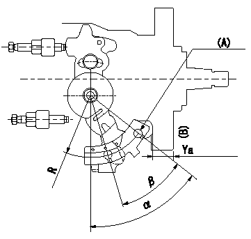
Control lever angle measurement
1. Measure dimension L between the end of the lever and the flange face.
2. Measure the lever angle from the pin hole R (plate).
(A) = lever angle measuring position
(B) = flange face
----------
L=10.7~14.2mm R=49mm
----------
L=10.7~14.2mm R=49mm
----------
L=10.7~14.2mm R=49mm
----------
L=10.7~14.2mm R=49mm
0000001901 ACCELERATOR SWITCH ADJ
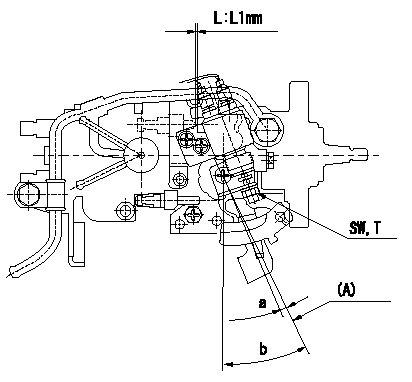
Adjustment of the accelerator switch
ON - OFF changeover point: from idle to c (shim thickness L = L1)
Idle-d: ON
e-full: OFF
L:Thickness of the shim
(A): Position of the idle lever
----------
c=5+-2deg d=5deg e=5deg L1=3.3+-0.13mm
----------
SW=SW10 T=6~9N-m(0.6~0.9Kgf-m) a=5+-2deg b=(25+-2)deg L1=3.3mm
----------
c=5+-2deg d=5deg e=5deg L1=3.3+-0.13mm
----------
SW=SW10 T=6~9N-m(0.6~0.9Kgf-m) a=5+-2deg b=(25+-2)deg L1=3.3mm
Information:
Oils that have more than 1% total sulfated ash should not be used in aftertreatment device equipped engines.In order to achieve expected ash service intervals, performance, and life, aftertreatment device equipped diesel engines require the use of Cat DEO-ULS or oils meeting the Cat ECF-3 specification and the API CJ-4 oil category. Use of oils with more than 1% total sulfated ash in aftertreatment device equipped engines will cause the need for more frequent ash service intervals, and/or cause loss of performance. Refer to your engine specific Operation and Maintenance Manual, and refer to your aftertreatment device documentation for additional guidance.
API category oils that have not met the requirements of at least one Cat ECF specification may cause reduced engine life.
In selecting oil for any engine application, both the oil viscosity and oil performance category/specification as specified by the engine manufacturer must be defined and satisfied. Using only one of these parameters will not sufficiently define oil for an engine application.
In order to make the proper diesel engine oil viscosity grade choice, refer to the applicable “Lubricant Viscosities for Ambient Temperatures” table in this Special Publication.
Failure to follow these oil recommendations can cause shortened engine service life due to deposits and/or excessive wear.
Total Base Number (TBN) and Fuel Sulfur Levels for Direct Injection (DI) Diesel Engines
The minimum required Total Base Number (TBN) for oil depends on the fuel sulfur level. The TBN for new oil is typically determined by the "ASTM D2896" procedure. For direct injection engines that use distillate fuel, the following guidelines apply.
Table 3
TBN recommendations for applications in Cat engines
Fuel Sulfur Level percent (ppm) Cat Engine Oils TBN of Commercial Engine Oils
≤0.05 percent (≤500 ppm) Cat DEO-ULS, Cat DEO Min 7
0. 1 - 0.05 percent (1000-500 ppm) Cat DEO-ULS, Cat DEO Min 7
Above 0.1 percent (above 1000 ppm) Cat DEO Min 10 Reaching one half of new oil TBN is one of the condemning factors for diesel engine oil. In order to help provide the best protection for your engine, Cat S O S Services oil analysis is the preferred method for determining oil life. TBN of the oil is typically measured using "ASTM D2896" and/or the "ASTM D4739" test methods. It is recommended to change the oil when one half of new oil TBN with either method is reached.For example, new oil with a TBN of 10 by "ASTM D2896" should be changed when, during use, the TBN deteriorates to 5 as determined by the "ASTM D2896" test method. New oil with a TBN of 10 by "ASTM D4739" should be changed when, during use, the TBN deteriorates to 5 as determined by the "ASTM D4739" test method.Note: TBN is also commonly referred to as Base Number (BN).Excessive piston deposits can be produced by oil with a high TBN and/or high ash. These deposits can lead to a loss of control of the oil consumption and to the polishing of the cylinder bore.The use of Cat S O S Services oil analysis helps the environmental