Information injection-pump assembly
ZEXEL
104740-9900
1047409900
NISSAN-DIESEL
1670022T02
1670022t02

Rating:
Components :
| 0. | INJECTION-PUMP ASSEMBLY | 104740-9900 |
| 1. | _ | |
| 2. | FUEL INJECTION PUMP | |
| 3. | NUMBER PLATE | |
| 4. | _ | |
| 5. | CAPSULE | |
| 6. | ADJUSTING DEVICE | |
| 7. | NOZZLE AND HOLDER ASSY | 105148-1121 |
| 8. | Nozzle and Holder | |
| 9. | Open Pre:MPa(Kqf/cm2) | 9.8(100) |
| 10. | NOZZLE-HOLDER | 105078-0050 |
| 11. | NOZZLE | 105007-1130 |
Include in #2:
104740-9900
as INJECTION-PUMP ASSEMBLY
Cross reference number
ZEXEL
104740-9900
1047409900
NISSAN-DIESEL
1670022T02
1670022t02
Zexel num
Bosch num
Firm num
Name
Calibration Data:
Adjustment conditions
Test oil
1404 Test oil ISO4113orSAEJ967d
1404 Test oil ISO4113orSAEJ967d
Test oil temperature
degC
45
45
50
Nozzle
105000-2010
Bosch type code
NP-DN12SD12TT
Nozzle holder
105780-2080
Opening pressure
MPa
14.7
14.7
15.19
Opening pressure
kgf/cm2
150
150
155
Injection pipe
Inside diameter - outside diameter - length (mm) mm 2-6-840
Inside diameter - outside diameter - length (mm) mm 2-6-840
Transfer pump pressure
kPa
20
20
20
Transfer pump pressure
kgf/cm2
0.2
0.2
0.2
Direction of rotation (viewed from drive side)
Right R
Right R
(Solenoid timer adjustment condition)
OFF
Injection timing adjustment
Pump speed
r/min
1100
1100
1100
Average injection quantity
mm3/st.
52.2
51.7
52.7
Difference in delivery
mm3/st.
3
Basic
*
Injection timing adjustment_02
Pump speed
r/min
2550
2550
2550
Average injection quantity
mm3/st.
10.1
5.6
14.6
Injection timing adjustment_03
Pump speed
r/min
2350
2350
2350
Average injection quantity
mm3/st.
33
30.5
35.5
Injection timing adjustment_04
Pump speed
r/min
2150
2150
2150
Average injection quantity
mm3/st.
42.9
40.8
45
Injection timing adjustment_05
Pump speed
r/min
1100
1100
1100
Average injection quantity
mm3/st.
52.2
51.2
53.2
Injection timing adjustment_06
Pump speed
r/min
600
600
600
Average injection quantity
mm3/st.
52.8
50.8
54.8
Injection quantity adjustment
Pump speed
r/min
2350
2350
2350
Average injection quantity
mm3/st.
33
31
35
Basic
*
Injection quantity adjustment_02
Pump speed
r/min
2700
2700
2700
Average injection quantity
mm3/st.
5
Governor adjustment
Pump speed
r/min
350
350
350
Average injection quantity
mm3/st.
7.3
5.3
9.3
Difference in delivery
mm3/st.
2
Basic
*
Governor adjustment_02
Pump speed
r/min
350
350
350
Average injection quantity
mm3/st.
7.3
5.3
9.3
Governor adjustment_03
Pump speed
r/min
450
450
450
Average injection quantity
mm3/st.
3
Timer adjustment
Pump speed
r/min
100
100
100
Average injection quantity
mm3/st.
62.5
45
80
Basic
*
Speed control lever angle
Pump speed
r/min
350
350
350
Average injection quantity
mm3/st.
0
0
0
Remarks
Magnet OFF
Magnet OFF
0000000901
Pump speed
r/min
1100
1100
1100
Overflow quantity
cm3/min
390
258
522
_02
Pump speed
r/min
1100
1100
1100
Overflow quantity
cm3/min
489
360
618
Remarks
Without an O-ring
Without an O-ring
Stop lever angle
Pump speed
r/min
1100
1100
1100
Pressure with S/T ON
kPa
480.5
441
520
Pressure with S/T ON
kgf/cm2
4.9
4.5
5.3
Pressure with S/T OFF
kPa
372.5
343
402
Pressure with S/T OFF
kgf/cm2
3.8
3.5
4.1
Basic
*
Stop lever angle_02
Pump speed
r/min
1100
1100
1100
Pressure with S/T ON
kPa
480.5
441
520
Pressure with S/T ON
kgf/cm2
4.9
4.5
5.3
Pressure with S/T OFF
kPa
372.5
343
402
Pressure with S/T OFF
kgf/cm2
3.8
3.5
4.1
Stop lever angle_03
Pump speed
r/min
1700
1700
1700
Pressure with S/T ON
kPa
618
579
657
Pressure with S/T ON
kgf/cm2
6.3
5.9
6.7
Pressure with S/T OFF
kPa
510
481
539
Pressure with S/T OFF
kgf/cm2
5.2
4.9
5.5
Stop lever angle_04
Pump speed
r/min
2150
2150
2150
Pressure with S/T OFF
kPa
598.5
569
628
Pressure with S/T OFF
kgf/cm2
6.1
5.8
6.4
0000001101
Pump speed
r/min
1100
1100
1100
Timer stroke with S/T ON
mm
4.3
3.9
4.7
Timer stroke with S/T OFF
mm
2.6
2.4
2.8
Basic
*
_02
Pump speed
r/min
1100
1100
1100
Timer stroke with S/T ON
mm
4.3
3.8
4.8
Timer stroke with S/T OFF
mm
2.6
2.3
2.9
_03
Pump speed
r/min
1700
1700
1700
Timer stroke with S/T OFF
mm
4.9
4.3
5.5
_04
Pump speed
r/min
2550
2550
2550
Timer stroke with S/T OFF
mm
7.3
6.8
7.8
0000001201
Max. applied voltage
V
16
16
16
Test voltage
V
25
24
26
Timing setting
K dimension
mm
3.3
3.2
3.4
KF dimension
mm
5.8
5.7
5.9
MS dimension
mm
0.9
0.8
1
Control lever angle alpha
deg.
54
50
58
Control lever angle beta
deg.
36
31
41
Test data Ex:
0000001801 CONTROL LEVER ANGLE
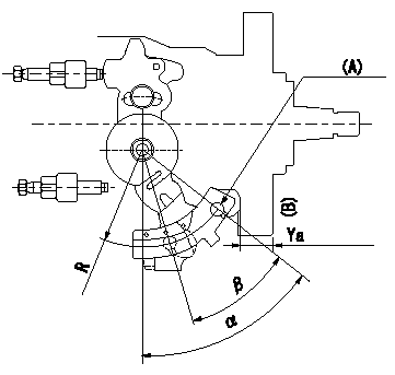
Control lever angle measurement
1. Measure dimension L between the end of the lever and the flange face.
2. Measure the lever angle from the pin hole R (plate).
(A) = lever angle measuring position
(B) = flange face
----------
L=10.7~14.2mm R=49mm
----------
L=10.7~14.2mm R=49mm
----------
L=10.7~14.2mm R=49mm
----------
L=10.7~14.2mm R=49mm
Information:
Table 2
Specifications for Pressure Loss
Direct Injection Fuel Systems
Nozzle pressure must not drop below a gauge reading of
3450 kPa (500 psi) during a 5 second time interval.
Nozzle pressure must drop below a gauge reading of
1380 kPa (200 psi) after an additional 25 second time interval. (1)
( 1 ) A gauge reading of 0 kPa (0 psi) is acceptable after the first 5 second time interval has elapsed.
Illustration 3 g00923167
If the fuel nozzle is not within specifications, stop the test and do not use the fuel nozzle.Valve Opening Pressure Test
Slowly increase the pressure until fluid begins to flow from the tip of the fuel nozzle. Record this pressure as the VOP of the fuel nozzle.
Compare the test results to the specifications for the type of fuel nozzle that is being tested. Refer to Table 3, or Table 4.For precombustion chamber fuel systems, use these specifications:
Table 3
Specifications for Valve Opening Pressure
Precombustion Chamber Fuel Systems
2760 to 5170 kPa (400 to 750 psi)
Illustration 4 g00934108
If the VOP is not within specifications, stop the test and do not use the fuel nozzle.For direct injection fuel systems, use these specifications:
Table 4
Specifications for Valve Opening Pressure
Direct Injection Fuel Systems
16500 to 21400 kPa (2400 to 3100 psi)
Illustration 5 g00923174
If the VOP is not within specifications, stop the test and do not use the fuel nozzle.Tip Leakage Test (Direct Injection Fuel Systems)
Note: Fuel nozzles for precombustion chamber fuel systems can not be tested for tip leakage accurately. Do not perform this test on fuel nozzles for a precombustion