Information injection-pump assembly
ZEXEL
104740-9890
1047409890
NISSAN-DIESEL
1670022T01
1670022t01

Rating:
Cross reference number
ZEXEL
104740-9890
1047409890
NISSAN-DIESEL
1670022T01
1670022t01
Zexel num
Bosch num
Firm num
Name
Calibration Data:
Adjustment conditions
Test oil
1404 Test oil ISO4113orSAEJ967d
1404 Test oil ISO4113orSAEJ967d
Test oil temperature
degC
45
45
50
Nozzle
105000-2010
Bosch type code
NP-DN12SD12TT
Nozzle holder
105780-2080
Opening pressure
MPa
14.7
14.7
15.19
Opening pressure
kgf/cm2
150
150
155
Injection pipe
Inside diameter - outside diameter - length (mm) mm 2-6-840
Inside diameter - outside diameter - length (mm) mm 2-6-840
Transfer pump pressure
kPa
20
20
20
Transfer pump pressure
kgf/cm2
0.2
0.2
0.2
Direction of rotation (viewed from drive side)
Right R
Right R
Injection timing adjustment
Pump speed
r/min
1100
1100
1100
Average injection quantity
mm3/st.
52.2
51.7
52.7
Difference in delivery
mm3/st.
3
Basic
*
Injection timing adjustment_02
Pump speed
r/min
2550
2550
2550
Average injection quantity
mm3/st.
10.1
5.6
14.6
Injection timing adjustment_03
Pump speed
r/min
2350
2350
2350
Average injection quantity
mm3/st.
33
30.5
35.5
Injection timing adjustment_04
Pump speed
r/min
2150
2150
2150
Average injection quantity
mm3/st.
42.9
40.8
45
Injection timing adjustment_05
Pump speed
r/min
1100
1100
1100
Average injection quantity
mm3/st.
52.2
51.2
53.2
Injection timing adjustment_06
Pump speed
r/min
600
600
600
Average injection quantity
mm3/st.
52.8
50.8
54.8
Injection quantity adjustment
Pump speed
r/min
2350
2350
2350
Average injection quantity
mm3/st.
33
31
35
Basic
*
Injection quantity adjustment_02
Pump speed
r/min
2700
2700
2700
Average injection quantity
mm3/st.
5
Governor adjustment
Pump speed
r/min
350
350
350
Average injection quantity
mm3/st.
7.3
5.3
9.3
Difference in delivery
mm3/st.
2
Basic
*
Governor adjustment_02
Pump speed
r/min
350
350
350
Average injection quantity
mm3/st.
7.3
5.3
9.3
Governor adjustment_03
Pump speed
r/min
400
400
400
Average injection quantity
mm3/st.
3
Timer adjustment
Pump speed
r/min
100
100
100
Average injection quantity
mm3/st.
62.5
45
80
Basic
*
Speed control lever angle
Pump speed
r/min
350
350
350
Average injection quantity
mm3/st.
0
0
0
Remarks
Magnet OFF
Magnet OFF
0000000901
Pump speed
r/min
1100
1100
1100
Overflow quantity
cm3/min
390
258
522
Stop lever angle
Pump speed
r/min
1100
1100
1100
Pressure
kPa
431.5
402
461
Pressure
kgf/cm2
4.4
4.1
4.7
Basic
*
Stop lever angle_02
Pump speed
r/min
1100
1100
1100
Pressure
kPa
431.5
402
461
Pressure
kgf/cm2
4.4
4.1
4.7
Stop lever angle_03
Pump speed
r/min
1700
1700
1700
Pressure
kPa
578.5
549
608
Pressure
kgf/cm2
5.9
5.6
6.2
Stop lever angle_04
Pump speed
r/min
2150
2150
2150
Pressure
kPa
676.5
647
706
Pressure
kgf/cm2
6.9
6.6
7.2
0000001101
Pump speed
r/min
1100
1100
1100
Timer stroke
mm
2.6
2.4
2.8
Basic
*
_02
Pump speed
r/min
1100
1100
1100
Timer stroke
mm
2.6
2.3
2.9
_03
Pump speed
r/min
1700
1700
1700
Timer stroke
mm
4.9
4.3
5.5
_04
Pump speed
r/min
2550
2550
2550
Timer stroke
mm
7.3
6.8
7.8
0000001201
Max. applied voltage
V
8
8
8
Test voltage
V
13
12
14
Timing setting
K dimension
mm
3.3
3.2
3.4
KF dimension
mm
5.8
5.7
5.9
MS dimension
mm
0.9
0.8
1
Control lever angle alpha
deg.
54
50
58
Control lever angle beta
deg.
36
31
41
Test data Ex:
0000001801 CONTROL LEVER ANGLE
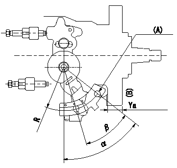
Control lever angle measurement
1. Measure dimension L between the end of the lever and the flange face.
2. Measure the lever angle from the pin hole R (plate).
(A) = lever angle measuring position
(B) = flange face
----------
L=10.7~14.2mm R=49mm
----------
L=10.7~14.2mm R=49mm
----------
L=10.7~14.2mm R=49mm
----------
L=10.7~14.2mm R=49mm
0000001901 ACCELERATOR SWITCH ADJ
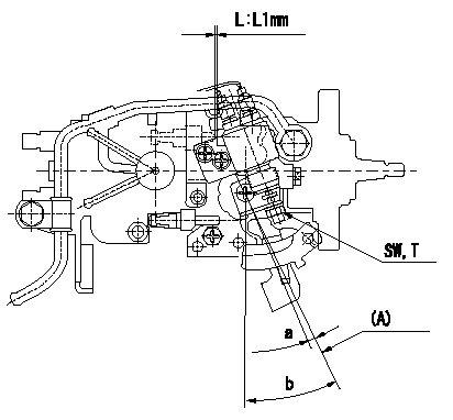
Adjustment of the accelerator switch
ON - OFF changeover point: from idle to c (shim thickness L = L1)
Idle-d: ON
e-full: OFF
L:Thickness of the shim
(A): Position of the idle lever
----------
c=5+-2deg d=5deg e=5deg L1=3.3+-0.13mm
----------
SW=SW10 T=6~9N-m(0.6~0.9Kgf-m) a=5+-2deg b=(25+-2)deg L1=3.3mm
----------
c=5+-2deg d=5deg e=5deg L1=3.3+-0.13mm
----------
SW=SW10 T=6~9N-m(0.6~0.9Kgf-m) a=5+-2deg b=(25+-2)deg L1=3.3mm
Information:
Personal injury can result from being struck by parts propelled by a released spring force.Make sure to wear all necessary protective equipment.Follow the recommended procedure and use all recommended tooling to release the spring force.
Care must be taken to ensure that fluids are contained during performance of inspection, maintenance, testing, adjusting and repair of the product. Be prepared to collect the fluid with suitable containers before opening any compartment or disassembling any component containing fluids.Dispose of all fluids according to local regulations and mandates.
If possible, take the fuel injection pump to a clean work area.
Clean the outside surfaces of the fuel injection pump.
Illustration 1 g03117860
Typical example
Place a suitable container under the fuel injection pump to collect any fuel from the fuel injection pump. Use a suitable tool to loosen the drain plug (1). If necessary, retain the fuel collected for analysis if required.
Illustration 2 g03117878
Typical example
Use a suitable pair of pliers to remove the throttle return spring (2).Note: Care should be taken when the spring is removed.
Illustration 3 g03117896
Typical example
Loosen self-locking nut (3). Do not remove the nut.
Illustration 4 g03117916
Typical example
Use a suitable pair of pliers to lift and disconnect throttle spring (4). Remove self-locking nut (3), washer, upper retainer, spring, lower retainer, spacer, lever, and dust cap.Note: Care should be taken when the spring is removed.
Illustration 5 g03117938
Typical example
Remove four screws (6) in the governor cover (7). Gently push the throttle shaft (5) down into the cover (7).
Illustration 6 g03117956
Typical example
To inspect the internal components of the fuel injection pump, gently lift and rotate the cover (7).Note: The cover is still connected internally, if resistance is felt, lower the cover and move the cover backwards. Attempt to lift the cover again.
Inspect the internal components of the fuel injection pump. Refer to steps 9a and 9b.
Illustration 7 g03117961
Typical example
If good quality fuel is being used, the components will be clean. Refer to illustration 7. Take photographs of the identification plate of the fuel injection pump and any evidence found. Attach the photographs to support the claim story.
Illustration 8 g03118119
Typical example
Illustration 9 g03118121
Typical example
If the injection pump has been run with excessive water in the fuel, there will be signs of rust and oxidization of the steel components. Refer to illustration 8. Fuel with dirt ingress will show a build-up of dirt on the components. Refer to illustration 9.Note: Issues with the fuel injection pump that are due to dirt and water void Caterpillar warranty. Advise the customer on the correct fuel, maintenance, and fuel storage procedures. Refer to the relevant Operation and Maintenance Manual for more information.If the fuel injection pump shows signs that contaminated fuel is the root cause of the problem, the evidence can be shown to the customer immediately.After the fuel injection pump has been inspected, the fuel injection pump must not be used in service.Rebuild the fuel injection pump. Refer to steps 1 to 6
Lower the cover (7) back into position. Ensure the throttle shaft (5), has been returned to the original position.
Install the four screws (6) to the cover (7). Tighten the