Information injection-pump assembly
ZEXEL
104740-9880
1047409880
NISSAN-DIESEL
1670022T00
1670022t00
Rating:
Components :
| 0. | INJECTION-PUMP ASSEMBLY | 104740-9880 |
| 1. | _ | |
| 2. | FUEL INJECTION PUMP | |
| 3. | NUMBER PLATE | |
| 4. | _ | |
| 5. | CAPSULE | |
| 6. | ADJUSTING DEVICE | |
| 7. | NOZZLE AND HOLDER ASSY | |
| 8. | Nozzle and Holder | |
| 9. | Open Pre:MPa(Kqf/cm2) | 9.8(100) |
| 10. | NOZZLE-HOLDER | 105078-0050 |
| 11. | NOZZLE | 105007-1130 |
Include in #2:
104740-9880
as INJECTION-PUMP ASSEMBLY
Cross reference number
ZEXEL
104740-9880
1047409880
NISSAN-DIESEL
1670022T00
1670022t00
Zexel num
Bosch num
Firm num
Name
Calibration Data:
Adjustment conditions
Test oil
1404 Test oil ISO4113orSAEJ967d
1404 Test oil ISO4113orSAEJ967d
Test oil temperature
degC
45
45
50
Nozzle
105000-2010
Bosch type code
NP-DN12SD12TT
Nozzle holder
105780-2080
Opening pressure
MPa
14.7
14.7
15.19
Opening pressure
kgf/cm2
150
150
155
Injection pipe
Inside diameter - outside diameter - length (mm) mm 2-6-840
Inside diameter - outside diameter - length (mm) mm 2-6-840
Transfer pump pressure
kPa
20
20
20
Transfer pump pressure
kgf/cm2
0.2
0.2
0.2
Direction of rotation (viewed from drive side)
Right R
Right R
Injection timing adjustment
Pump speed
r/min
1100
1100
1100
Average injection quantity
mm3/st.
52.2
51.7
52.7
Difference in delivery
mm3/st.
3
Basic
*
Injection timing adjustment_02
Pump speed
r/min
2550
2550
2550
Average injection quantity
mm3/st.
10.1
5.6
14.6
Injection timing adjustment_03
Pump speed
r/min
2350
2350
2350
Average injection quantity
mm3/st.
34.2
32.2
36.2
Injection timing adjustment_04
Pump speed
r/min
2150
2150
2150
Average injection quantity
mm3/st.
42.9
40.8
45
Injection timing adjustment_05
Pump speed
r/min
1100
1100
1100
Average injection quantity
mm3/st.
52.3
51.3
53.3
Injection timing adjustment_06
Pump speed
r/min
600
600
600
Average injection quantity
mm3/st.
52.8
50.8
54.8
Injection quantity adjustment
Pump speed
r/min
2350
2350
2350
Average injection quantity
mm3/st.
33
31
35
Basic
*
Injection quantity adjustment_02
Pump speed
r/min
2700
2700
2700
Average injection quantity
mm3/st.
5
Governor adjustment
Pump speed
r/min
350
350
350
Average injection quantity
mm3/st.
7.3
5.3
9.3
Difference in delivery
mm3/st.
2
Basic
*
Governor adjustment_02
Pump speed
r/min
350
350
350
Average injection quantity
mm3/st.
7.3
5.3
9.3
Governor adjustment_03
Pump speed
r/min
450
450
450
Average injection quantity
mm3/st.
3
Timer adjustment
Pump speed
r/min
100
100
100
Average injection quantity
mm3/st.
62.5
45
80
Basic
*
Speed control lever angle
Pump speed
r/min
350
350
350
Average injection quantity
mm3/st.
0
0
0
Remarks
Magnet OFF
Magnet OFF
0000000901
Pump speed
r/min
1100
1100
1100
Overflow quantity
cm3/min
390
258
522
Stop lever angle
Pump speed
r/min
1100
1100
1100
Pressure
kPa
431.5
402
461
Pressure
kgf/cm2
4.4
4.1
4.7
Basic
*
Stop lever angle_02
Pump speed
r/min
1100
1100
1100
Pressure
kPa
431.5
402
461
Pressure
kgf/cm2
4.4
4.1
4.7
Stop lever angle_03
Pump speed
r/min
1700
1700
1700
Pressure
kPa
578.5
549
608
Pressure
kgf/cm2
5.9
5.6
6.2
Stop lever angle_04
Pump speed
r/min
2150
2150
2150
Pressure
kPa
676.5
647
706
Pressure
kgf/cm2
6.9
6.6
7.2
0000001101
Pump speed
r/min
1100
1100
1100
Timer stroke
mm
2.6
2.4
2.8
Basic
*
_02
Pump speed
r/min
1100
1100
1100
Timer stroke
mm
2.6
2.3
2.9
_03
Pump speed
r/min
1700
1700
1700
Timer stroke
mm
4.9
4.4
5.4
_04
Pump speed
r/min
2550
2550
2550
Timer stroke
mm
7.3
6.8
7.8
0000001201
Max. applied voltage
V
8
8
8
Test voltage
V
13
12
14
Timing setting
K dimension
mm
3.3
3.2
3.4
KF dimension
mm
5.8
5.7
5.9
MS dimension
mm
0.9
0.8
1
Control lever angle alpha
deg.
54
50
58
Control lever angle beta
deg.
36
31
41
Test data Ex:
0000001801 CONTROL LEVER ANGLE
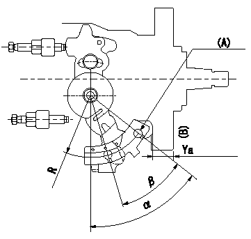
Control lever angle measurement
1. Measure dimension L between the end of the lever and the flange face.
2. Measure the lever angle from the pin hole R (plate).
(A) = lever angle measuring position
(B) = flange face
----------
L=10.7~14.2mm R=49mm
----------
L=10.7~14.2mm R=49mm
----------
L=10.7~14.2mm R=49mm
----------
L=10.7~14.2mm R=49mm
Information:
Disconnect all electrical power from the monitor before removing components. Failure to disconnect the power could result in severe electrical shock or damage to the monitor. An electrical shock can cause severe personal injury or death.
Choose the appropriate drive for your monitor from the table below. The 203-7811 Engine Monitoring Control Group uses Wonderware as the "Graphic Display Application". The 203-7810 Engine Monitoring Control Group uses RSView as the "Graphic Display Application".
Table 1
Drive "Graphic Display Application"
203-7816 Storage Drive RSView
204-8792 Storage Drive Wonderware In order to install the drive, perform the procedure that follows:
Connect the ribbon cable connector and power cables to the hard drive and the floppy disk drive.Note: Make sure that the ribbon cable is correctly installed. The connector must be positioned so that the red wire of the cable is closest to the back of the unit. If you are using the new cables, also connect the other end of the cables to the Central Processing Unit (CPU) card.
Illustration 1 g00858453
(1) Drive Bay Mounting Studs
Position the drive bay into the chassis so that the studs (1) on the chassis fit into the grommets on the drive bay.Note: Be careful not to push the vibration dampers (grommets) on the drive bay out of the sheet metal.
Install the back cover.
Apply power and verify the operation of the drive. Refer to any additional instructions that are provided with the drive.