Information injection-pump assembly
ZEXEL
104740-9830
1047409830
NISSAN-DIESEL
1670021T06
1670021t06
Rating:
Cross reference number
ZEXEL
104740-9830
1047409830
NISSAN-DIESEL
1670021T06
1670021t06
Zexel num
Bosch num
Firm num
Name
Calibration Data:
Adjustment conditions
Test oil
1404 Test oil ISO4113orSAEJ967d
1404 Test oil ISO4113orSAEJ967d
Test oil temperature
degC
45
45
50
Nozzle
105000-2010
Bosch type code
NP-DN12SD12TT
Nozzle holder
105780-2080
Opening pressure
MPa
14.7
14.7
15.19
Opening pressure
kgf/cm2
150
150
155
Injection pipe
Inside diameter - outside diameter - length (mm) mm 2-6-840
Inside diameter - outside diameter - length (mm) mm 2-6-840
Transfer pump pressure
kPa
20
20
20
Transfer pump pressure
kgf/cm2
0.2
0.2
0.2
Direction of rotation (viewed from drive side)
Right R
Right R
(Solenoid timer adjustment condition)
OFF
Injection timing adjustment
Pump speed
r/min
1100
1100
1100
Average injection quantity
mm3/st.
44.6
44.1
45.1
Difference in delivery
mm3/st.
3
Basic
*
Injection timing adjustment_02
Pump speed
r/min
2550
2550
2550
Average injection quantity
mm3/st.
8.85
5.3
12.4
Injection timing adjustment_03
Pump speed
r/min
2350
2350
2350
Average injection quantity
mm3/st.
30.3
27.8
32.8
Injection timing adjustment_04
Pump speed
r/min
2150
2150
2150
Average injection quantity
mm3/st.
38
35.9
40.1
Injection timing adjustment_05
Pump speed
r/min
1100
1100
1100
Average injection quantity
mm3/st.
44.6
43.6
45.6
Injection timing adjustment_06
Pump speed
r/min
600
600
600
Average injection quantity
mm3/st.
43.5
41.5
45.5
Injection quantity adjustment
Pump speed
r/min
2350
2350
2350
Average injection quantity
mm3/st.
30.3
28.3
32.3
Basic
*
Injection quantity adjustment_02
Pump speed
r/min
2700
2700
2700
Average injection quantity
mm3/st.
5
Governor adjustment
Pump speed
r/min
350
350
350
Average injection quantity
mm3/st.
6.5
4.5
8.5
Difference in delivery
mm3/st.
2
Basic
*
Governor adjustment_02
Pump speed
r/min
350
350
350
Average injection quantity
mm3/st.
6.5
4.5
8.5
Governor adjustment_03
Pump speed
r/min
400
400
400
Average injection quantity
mm3/st.
2
Timer adjustment
Pump speed
r/min
100
100
100
Average injection quantity
mm3/st.
62.5
45
80
Basic
*
Speed control lever angle
Pump speed
r/min
350
350
350
Average injection quantity
mm3/st.
0
0
0
Remarks
Magnet OFF
Magnet OFF
0000000901
Pump speed
r/min
1100
1100
1100
Overflow quantity with S/T OFF
cm3/min
390
258
522
_02
Pump speed
r/min
1100
1100
1100
Overflow quantity with S/T OFF
cm3/min
489
360
618
Remarks
Without an O-ring
Without an O-ring
Stop lever angle
Pump speed
r/min
1700
1700
1700
Pressure with S/T ON
kPa
618
579
657
Pressure with S/T ON
kgf/cm2
6.3
5.9
6.7
Pressure with S/T OFF
kPa
510
481
539
Pressure with S/T OFF
kgf/cm2
5.2
4.9
5.5
Basic
*
Stop lever angle_02
Pump speed
r/min
1100
1100
1100
Pressure with S/T ON
kPa
480.5
441
520
Pressure with S/T ON
kgf/cm2
4.9
4.5
5.3
Pressure with S/T OFF
kPa
372.5
343
402
Pressure with S/T OFF
kgf/cm2
3.8
3.5
4.1
Stop lever angle_03
Pump speed
r/min
1700
1700
1700
Pressure with S/T ON
kPa
618
579
657
Pressure with S/T ON
kgf/cm2
6.3
5.9
6.7
Pressure with S/T OFF
kPa
510
481
539
Pressure with S/T OFF
kgf/cm2
5.2
4.9
5.5
Stop lever angle_04
Pump speed
r/min
2150
2150
2150
Pressure with S/T OFF
kPa
598.5
569
628
Pressure with S/T OFF
kgf/cm2
6.1
5.8
6.4
0000001101
Pump speed
r/min
1700
1700
1700
Timer stroke with S/T ON
mm
6.2
5.8
6.6
Timer stroke with S/T OFF
mm
4.6
4.4
4.8
Basic
*
_02
Pump speed
r/min
1100
1100
1100
Timer stroke with S/T OFF
mm
2.5
2.1
2.9
_03
Pump speed
r/min
1700
1700
1700
Timer stroke with S/T ON
mm
6.2
5.7
6.7
Timer stroke with S/T OFF
mm
4.6
4.3
4.9
_04
Pump speed
r/min
2550
2550
2550
Timer stroke with S/T OFF
mm
6.9
6.4
7.4
0000001201
Max. applied voltage
V
8
8
8
Test voltage
V
13
12
14
Timing setting
K dimension
mm
3.3
3.2
3.4
KF dimension
mm
5.8
5.7
5.9
MS dimension
mm
1
0.9
1.1
Control lever angle alpha
deg.
54
50
58
Control lever angle beta
deg.
36
31
41
Test data Ex:
0000001801 CONTROL LEVER ANGLE
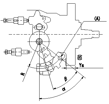
Control lever angle measurement
1. Measure dimension L between the end of the lever and the flange face.
2. Measure the lever angle from the pin hole R (plate).
(A) = lever angle measuring position
(B) = flange face
----------
L=10.7~14.2mm R=49mm
----------
L=10.7~14.2mm R=49mm
----------
L=10.7~14.2mm R=49mm
----------
L=10.7~14.2mm R=49mm
Information:
Touchscreen Serial Port Usage
The optional touchscreen controller for a monitor connects internally to the "COM2" serial port. The touchscreen is configured at the factory with the proper "COM2" and touchscreen driver settings. Therefore, no configuration by the user is required. If the settings are corrupted, reset the "COM2" serial port to the following settings:
9600 bps
8 data bits
1 stop bit
no parityDriver Software
The touchscreen driver is already loaded on the monitor. The driver software is also provided on a floppy disk.Note: The Elo TouchSystems touchscreen utility defaults to the "COM1" serial port setting. Change the setting to the "COM2" serial port when the touchscreen driver is reinstalled.Resistive Touchsceen Technology
Resistive touchscreens are activated when pressure is applied to the touchscreen by the finger of an operator. You can operate a resistive touchsceen while you wear gloves.Note: Do not use sharp instruments to activate the touchscreen. Scratching the surface of the touchscreen could damage the unit.Resistive touchscreens consist of the following layers:
A lower layer (glass substrate) with a resistive coating and an applied voltage
An upper layer (cover sheet) with conductive coating
Clear spacer dots separate the two layers.The upper layer is pressed onto the lower layer by the user. The upper layer receives the voltage that is applied to the lower layer. The touchscreen controller detects the change in voltage on the upper layer. The touchscreen controller alternates the voltage horizontally through the layers. The touchscreen controller alternates the voltage vertically through the layers. The voltage that is transferred to the upper layer is proportional to the location of the touch on the screen.Calibrating the Touchscreen
The touchscreen that is supplied with the monitor is factory installed and calibrated. If the touchscreen needs to be recalibrated, perform the following procedure:
Locate the Elo calibration utility in the Control Panel or insert the touchscreen driver diskette in the floppy disk drive of the monitor.
Run the Elo calibration utility. Use appropriate commands for the operating system.
Follow the instructions in the Elo calibration utility in order to complete the calibration process.Maintenance
Routine Cleaning
Clean the surface of the touchscreen with any glass cleaning solution. Use a cloth that is soft and non-abrasive.Note: Because the touchscreen is sensitive to pressure, directing strong flow of water at the touchscreen during a washdown may activate the touchscreen.