Information injection-pump assembly
ZEXEL
104740-9820
1047409820
NISSAN-DIESEL
1670021T05
1670021t05

Rating:
Cross reference number
ZEXEL
104740-9820
1047409820
NISSAN-DIESEL
1670021T05
1670021t05
Zexel num
Bosch num
Firm num
Name
Calibration Data:
Adjustment conditions
Test oil
1404 Test oil ISO4113orSAEJ967d
1404 Test oil ISO4113orSAEJ967d
Test oil temperature
degC
45
45
50
Nozzle
105000-2010
Bosch type code
NP-DN12SD12TT
Nozzle holder
105780-2080
Opening pressure
MPa
14.7
14.7
15.19
Opening pressure
kgf/cm2
150
150
155
Injection pipe
Inside diameter - outside diameter - length (mm) mm 2-6-840
Inside diameter - outside diameter - length (mm) mm 2-6-840
Transfer pump pressure
kPa
20
20
20
Transfer pump pressure
kgf/cm2
0.2
0.2
0.2
Direction of rotation (viewed from drive side)
Right R
Right R
Injection timing adjustment
Pump speed
r/min
1100
1100
1100
Average injection quantity
mm3/st.
44.6
44.1
45.1
Difference in delivery
mm3/st.
3
Basic
*
Injection timing adjustment_02
Pump speed
r/min
2550
2550
2550
Average injection quantity
mm3/st.
8.85
5.3
12.4
Injection timing adjustment_03
Pump speed
r/min
2350
2350
2350
Average injection quantity
mm3/st.
30.3
27.8
32.8
Injection timing adjustment_04
Pump speed
r/min
2150
2150
2150
Average injection quantity
mm3/st.
38
35.9
40.1
Injection timing adjustment_05
Pump speed
r/min
1100
1100
1100
Average injection quantity
mm3/st.
44.6
43.6
45.6
Injection timing adjustment_06
Pump speed
r/min
600
600
600
Average injection quantity
mm3/st.
43.5
41.5
45.5
Injection quantity adjustment
Pump speed
r/min
2350
2350
2350
Average injection quantity
mm3/st.
30.3
28.3
32.3
Basic
*
Injection quantity adjustment_02
Pump speed
r/min
2700
2700
2700
Average injection quantity
mm3/st.
5
Governor adjustment
Pump speed
r/min
350
350
350
Average injection quantity
mm3/st.
6.5
4.5
8.5
Difference in delivery
mm3/st.
2
Basic
*
Governor adjustment_02
Pump speed
r/min
350
350
350
Average injection quantity
mm3/st.
6.5
4.5
8.5
Governor adjustment_03
Pump speed
r/min
400
400
400
Average injection quantity
mm3/st.
3
Timer adjustment
Pump speed
r/min
100
100
100
Average injection quantity
mm3/st.
62.5
45
80
Basic
*
Speed control lever angle
Pump speed
r/min
350
350
350
Average injection quantity
mm3/st.
0
0
0
Remarks
Magnet OFF
Magnet OFF
0000000901
Pump speed
r/min
1100
1100
1100
Overflow quantity
cm3/min
390
258
522
Stop lever angle
Pump speed
r/min
1700
1700
1700
Pressure
kPa
578.5
549
608
Pressure
kgf/cm2
5.9
5.6
6.2
Basic
*
Stop lever angle_02
Pump speed
r/min
1100
1100
1100
Pressure
kPa
431.5
402
461
Pressure
kgf/cm2
4.4
4.1
4.7
Stop lever angle_03
Pump speed
r/min
1700
1700
1700
Pressure
kPa
578.5
549
608
Pressure
kgf/cm2
5.9
5.6
6.2
Stop lever angle_04
Pump speed
r/min
2150
2150
2150
Pressure
kPa
676.5
647
706
Pressure
kgf/cm2
6.9
6.6
7.2
0000001101
Pump speed
r/min
1700
1700
1700
Timer stroke
mm
4.6
4.4
4.8
Basic
*
_02
Pump speed
r/min
1100
1100
1100
Timer stroke
mm
2.5
2.1
2.9
_03
Pump speed
r/min
1700
1700
1700
Timer stroke
mm
4.6
4.3
4.9
_04
Pump speed
r/min
2550
2550
2550
Timer stroke
mm
6.9
6.4
7.4
0000001201
Max. applied voltage
V
8
8
8
Test voltage
V
13
12
14
Timing setting
K dimension
mm
3.3
3.2
3.4
KF dimension
mm
5.8
5.7
5.9
MS dimension
mm
1
0.9
1.1
Control lever angle alpha
deg.
54
50
58
Control lever angle beta
deg.
36
31
41
Test data Ex:
0000001801 CONTROL LEVER ANGLE
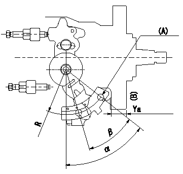
Control lever angle measurement
1. Measure dimension L between the end of the lever and the flange face.
2. Measure the lever angle from the pin hole R (plate).
(A) = lever angle measuring position
(B) = flange face
----------
L=10.7~14.2mm R=49mm
----------
L=10.7~14.2mm R=49mm
----------
L=10.7~14.2mm R=49mm
----------
L=10.7~14.2mm R=49mm
Information:
- Generator Monitoring SystemI/O - Input/OutputMMS - Marine Monitoring SystemMMS II - Marine Monitoring System IIPLC - Programmable Logic ControllerThe 203-7811 Engine Monitoring Control Group is the service replacement for the 146-3117 Monitoring Control and the 162-1662 Monitoring Control that are used in MMS. The 203-7811 Engine Monitoring Control Group uses Wonderware as the "Graphic Display Application".The 203-7810 Engine Monitoring Control Group is the optional monitor that is used in the MMS II and the GMS. The 203-7810 Engine Monitoring Control Group uses the RSView as the "Graphic Display Application".When these engine monitoring control groups are used as service replacements in the field, use the procedure that follows to register the software to the user. This procedure can be done when the engine monitoring control group is connected to the PLC. This procedure can also be done when the engine monitoring control group is not connected to the PLC.
Connect a keyboard that is compatible with the PS/2 style of connector. Connect electrical power to the monitor.
Turn on the power.
When you are prompted, accept the license agreement. Press the "Next" button.
Enter the Microsoft Windows NT product identification number. This number is located on the right side of the computer. Press "Next".
When the message indicates that the system could not complete the login, select "OK".
Input "Administrator" for the login username. Input "3600" for the login password.
After a successful login as "Administrator", do one of the items that follow:
Restart the computer.
Close all of the programs and use a different login username.
When the message indicates that the system could not complete the login, select "OK".
Input "Operator" for the login username. Input "password" for the login password.
After a successful login as "Operator", one of the items that follow will occur:
If a 203-7811 Engine Monitoring Control Group is used, the Wonderware I/O Server and the Window Viewer will be started.
If a 203-7810 Engine Monitoring Control Group is used, the RSView Runtime will be started.
Remove the keyboard. The setup is complete.In applications that use Wonderware or RSView, the engine monitoring control group must be connected to the PLC in order for the data to be displayed.After a successful login to the "Operator" account, the computer will automatically start and the computer will start the application in the "Operator" account. The automatic start-up can be bypassed by doing the operations that follow:
Attach a keyboard.
Hold the "shift" key in the down position while the start-up of the computer is initiated.