Information injection-pump assembly
ZEXEL
104740-9810
1047409810
NISSAN-DIESEL
1670021T04
1670021t04
Rating:
Cross reference number
ZEXEL
104740-9810
1047409810
NISSAN-DIESEL
1670021T04
1670021t04
Zexel num
Bosch num
Firm num
Name
Calibration Data:
Adjustment conditions
Test oil
1404 Test oil ISO4113orSAEJ967d
1404 Test oil ISO4113orSAEJ967d
Test oil temperature
degC
45
45
50
Nozzle
105000-2010
Bosch type code
NP-DN12SD12TT
Nozzle holder
105780-2080
Opening pressure
MPa
14.7
14.7
15.19
Opening pressure
kgf/cm2
150
150
155
Injection pipe
Inside diameter - outside diameter - length (mm) mm 2-6-840
Inside diameter - outside diameter - length (mm) mm 2-6-840
Transfer pump pressure
kPa
20
20
20
Transfer pump pressure
kgf/cm2
0.2
0.2
0.2
Direction of rotation (viewed from drive side)
Right R
Right R
(Solenoid timer adjustment condition)
OFF
Injection timing adjustment
Pump speed
r/min
1100
1100
1100
Average injection quantity
mm3/st.
44.6
44.1
45.1
Difference in delivery
mm3/st.
3
Basic
*
Injection timing adjustment_02
Pump speed
r/min
2550
2550
2550
Average injection quantity
mm3/st.
8.9
5.4
12.4
Injection timing adjustment_03
Pump speed
r/min
2350
2350
2350
Average injection quantity
mm3/st.
30.3
27.8
32.8
Injection timing adjustment_04
Pump speed
r/min
2150
2150
2150
Average injection quantity
mm3/st.
38
35.9
40.1
Injection timing adjustment_05
Pump speed
r/min
1100
1100
1100
Average injection quantity
mm3/st.
44.6
43.6
45.6
Injection timing adjustment_06
Pump speed
r/min
600
600
600
Average injection quantity
mm3/st.
43.5
41.5
45.5
Injection quantity adjustment
Pump speed
r/min
2350
2350
2350
Average injection quantity
mm3/st.
30.3
28.3
32.3
Basic
*
Injection quantity adjustment_02
Pump speed
r/min
2700
2700
2700
Average injection quantity
mm3/st.
5
Governor adjustment
Pump speed
r/min
350
350
350
Average injection quantity
mm3/st.
6.5
4.5
8.5
Difference in delivery
mm3/st.
2
Basic
*
Governor adjustment_02
Pump speed
r/min
350
350
350
Average injection quantity
mm3/st.
6.5
4.5
8.5
Governor adjustment_03
Pump speed
r/min
400
400
400
Average injection quantity
mm3/st.
3
Timer adjustment
Pump speed
r/min
100
100
100
Average injection quantity
mm3/st.
62.5
45
80
Basic
*
Speed control lever angle
Pump speed
r/min
350
350
350
Average injection quantity
mm3/st.
0
0
0
Remarks
Magnet OFF
Magnet OFF
0000000901
Pump speed
r/min
1100
1100
1100
Overflow quantity with S/T ON
cm3/min
390
258
522
_02
Pump speed
r/min
1100
1100
1100
Overflow quantity with S/T ON
cm3/min
489
360
618
Remarks
Without an O-ring
Without an O-ring
Stop lever angle
Pump speed
r/min
1100
1100
1100
Pressure with S/T ON
kPa
480.5
441
520
Pressure with S/T ON
kgf/cm2
4.9
4.5
5.3
Pressure with S/T OFF
kPa
372.5
343
402
Pressure with S/T OFF
kgf/cm2
3.8
3.5
4.1
Basic
*
Stop lever angle_02
Pump speed
r/min
1100
1100
1100
Pressure with S/T ON
kPa
480.5
441
520
Pressure with S/T ON
kgf/cm2
4.9
4.5
5.3
Pressure with S/T OFF
kPa
372.5
343
402
Pressure with S/T OFF
kgf/cm2
3.8
3.5
4.1
Stop lever angle_03
Pump speed
r/min
1700
1700
1700
Pressure with S/T ON
kPa
618
579
657
Pressure with S/T ON
kgf/cm2
6.3
5.9
6.7
Pressure with S/T OFF
kPa
510
481
539
Pressure with S/T OFF
kgf/cm2
5.2
4.9
5.5
Stop lever angle_04
Pump speed
r/min
2150
2150
2150
Pressure with S/T OFF
kPa
598.5
569
628
Pressure with S/T OFF
kgf/cm2
6.1
5.8
6.4
0000001101
Pump speed
r/min
1100
1100
1100
Timer stroke with S/T ON
mm
4.2
3.8
4.6
Timer stroke with S/T OFF
mm
2.5
2.3
2.7
Basic
*
_02
Pump speed
r/min
1100
1100
1100
Timer stroke with S/T ON
mm
4.2
3.7
4.7
Timer stroke with S/T OFF
mm
2.5
2.2
2.8
_03
Pump speed
r/min
1700
1700
1700
Timer stroke with S/T ON
mm
6.2
5.4
7
Timer stroke with S/T OFF
mm
4.6
4
5.2
_04
Pump speed
r/min
2550
2550
2550
Timer stroke with S/T OFF
mm
6.9
6.4
7.4
0000001201
Max. applied voltage
V
16
16
16
Test voltage
V
25
24
26
Timing setting
K dimension
mm
3.3
3.2
3.4
KF dimension
mm
5.8
5.7
5.9
MS dimension
mm
1
0.9
1.1
Control lever angle alpha
deg.
54
50
58
Control lever angle beta
deg.
36
31
41
Test data Ex:
0000001801 CONTROL LEVER ANGLE
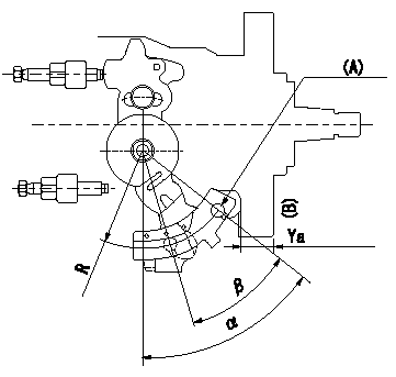
Control lever angle measurement
1. Measure dimension L between the end of the lever and the flange face.
2. Measure the lever angle from the pin hole R (plate).
(A) = lever angle measuring position
(B) = flange face
----------
L=10.7~14.2mm R=49mm
----------
L=10.7~14.2mm R=49mm
----------
L=10.7~14.2mm R=49mm
----------
L=10.7~14.2mm R=49mm
Information:
Disconnect all electrical power from the panel before making a panel cutout. Make sure the area around the panel cutout is clear. Take precautions to prevent metal cuttings from entering any components that are already installed in the panel. Failure to follow these instructions may result in personal injury or damage to the panel components.
Environmental Considerations
Mount the monitor in a panel or in an enclosure in order to protect the internal circuitry.Provide adequate ventilation in the enclosure. Also, consider heat produced by other devices in the enclosure. The ambient temperature around the monitor must be maintained between 5 °C (41 °F) and 50 °C (122 °F). Make sure that you provide provisions for accessing the back panel and side panels of the monitor. Installing components and removing components requires access to the panels. The floppy disk drive is also accessed through the panels. Refer to Illustration 1.
Illustration 1 g00857541
Mounting ClearancesNote: The dimensions in Illustration 1 are only applicable if the monitor has adequate ventilation. Cooling methods must be used in order to lower air temperature within the enclosure.Mounting Hardware
Table 1
Item Description Quantity Use For
Self-locking nuts #10-32 10 (8 required) Panel or enclosure mounting In addition to the tools that are required in order to make the cut for the panel, you will need the following tools:
Drill
9.525 mm (3/8 inch) socket
15 cm (6 inch) extension rod (minimum)
Socket driver (in/lb. torque wrench recommended)
RulerPanel Mounting
In order to install the monitor in a panel, perform the following procedure:
Cut an opening in the panel by using the dimensions that are provided. Drill eight 6.4 mm (0.25 inch) holes for the mounting studs. Refer to Installation, "Dimensions" for more information.
Make sure that the sealing gasket is properly positioned on the terminal. This gasket forms a compression seal. Do not use sealing compounds.
Place the monitor in the opening in the panel. Align the studs with the mounting holes.
Install the eight self-locking nuts. Hand tighten the self-locking nuts.
Illustration 2 g00857579
Torque Sequence
Alternately tighten the self-locking nuts with the 9.525 mm (3/8 inch) socket. Tighten the nuts until the monitor is held firmly against the panel. The amount of torque that is required increases significantly as the gasket reaches the proper compression. Tighten the nuts to a torque of 2.7 N m (24 lb in). Refer to Illustration 2 for the recommended tightening sequence.Note: Tighten the nuts to a torque of 2.7 N m (24 lb in) in order to provide a proper seal and prevent damage to the monitor.