Information injection-pump assembly
BOSCH
9 460 614 337
9460614337
ZEXEL
104740-9790
1047409790
NISSAN-DIESEL
1670021T02
1670021t02

Rating:
Cross reference number
BOSCH
9 460 614 337
9460614337
ZEXEL
104740-9790
1047409790
NISSAN-DIESEL
1670021T02
1670021t02
Zexel num
Bosch num
Firm num
Name
104740-9790
9 460 614 337
1670021T02 NISSAN-DIESEL
INJECTION-PUMP ASSEMBLY
TD25 K
TD25 K
Calibration Data:
Adjustment conditions
Test oil
1404 Test oil ISO4113orSAEJ967d
1404 Test oil ISO4113orSAEJ967d
Test oil temperature
degC
45
45
50
Nozzle
105000-2010
Bosch type code
NP-DN12SD12TT
Nozzle holder
105780-2080
Opening pressure
MPa
14.7
14.7
15.19
Opening pressure
kgf/cm2
150
150
155
Injection pipe
Inside diameter - outside diameter - length (mm) mm 2-6-840
Inside diameter - outside diameter - length (mm) mm 2-6-840
Transfer pump pressure
kPa
20
20
20
Transfer pump pressure
kgf/cm2
0.2
0.2
0.2
Direction of rotation (viewed from drive side)
Right R
Right R
Injection timing adjustment
Pump speed
r/min
1100
1100
1100
Average injection quantity
mm3/st.
48.5
48
49
Difference in delivery
mm3/st.
3
Basic
*
Injection timing adjustment_02
Pump speed
r/min
2500
2500
2500
Average injection quantity
mm3/st.
12.1
9.6
14.6
Injection timing adjustment_03
Pump speed
r/min
2300
2300
2300
Average injection quantity
mm3/st.
32.8
28.3
37.3
Injection timing adjustment_04
Pump speed
r/min
2150
2150
2150
Average injection quantity
mm3/st.
40.65
38.5
42.8
Injection timing adjustment_05
Pump speed
r/min
1100
1100
1100
Average injection quantity
mm3/st.
48.5
47.5
49.5
Injection timing adjustment_06
Pump speed
r/min
600
600
600
Average injection quantity
mm3/st.
47.1
45.1
49.1
Injection quantity adjustment
Pump speed
r/min
2500
2500
2500
Average injection quantity
mm3/st.
12.1
10.1
14.1
Basic
*
Injection quantity adjustment_02
Pump speed
r/min
2700
2700
2700
Average injection quantity
mm3/st.
5
Governor adjustment
Pump speed
r/min
350
350
350
Average injection quantity
mm3/st.
6.5
4.5
8.5
Difference in delivery
mm3/st.
2
Basic
*
Governor adjustment_02
Pump speed
r/min
350
350
350
Average injection quantity
mm3/st.
6.5
4.5
8.5
Governor adjustment_03
Pump speed
r/min
450
450
450
Average injection quantity
mm3/st.
3
Timer adjustment
Pump speed
r/min
100
100
100
Average injection quantity
mm3/st.
62.5
45
80
Basic
*
Speed control lever angle
Pump speed
r/min
350
350
350
Average injection quantity
mm3/st.
0
0
0
Remarks
Magnet OFF
Magnet OFF
0000000901
Pump speed
r/min
1100
1100
1100
Overflow quantity
cm3/min
390
258
522
Stop lever angle
Pump speed
r/min
1700
1700
1700
Pressure
kPa
578.5
549
608
Pressure
kgf/cm2
5.9
5.6
6.2
Basic
*
Stop lever angle_02
Pump speed
r/min
1100
1100
1100
Pressure
kPa
431.5
402
461
Pressure
kgf/cm2
4.4
4.1
4.7
Stop lever angle_03
Pump speed
r/min
1700
1700
1700
Pressure
kPa
578.5
549
608
Pressure
kgf/cm2
5.9
5.6
6.2
Stop lever angle_04
Pump speed
r/min
2150
2150
2150
Pressure
kPa
676.5
647
706
Pressure
kgf/cm2
6.9
6.6
7.2
0000001101
Pump speed
r/min
1700
1700
1700
Timer stroke
mm
4.9
4.7
5.1
Basic
*
_02
Pump speed
r/min
1100
1100
1100
Timer stroke
mm
2.6
2
3.2
_03
Pump speed
r/min
1700
1700
1700
Timer stroke
mm
4.9
4.6
5.2
_04
Pump speed
r/min
2300
2300
2300
Timer stroke
mm
6.5
6
7
0000001201
Max. applied voltage
V
8
8
8
Test voltage
V
13
12
14
0000001501
Pump speed
r/min
1100
1100
1100
Atmospheric pressure difference
kPa
-21.9
-22.6
-21.2
Atmospheric pressure difference
mmHg
-164
-169
-159
Average injection quantity
mm3/st.
37.6
36.1
39.1
Basic
*
_02
Pump speed
r/min
1100
1100
1100
Atmospheric pressure difference
kPa
-21.9
-22.6
-21.2
Atmospheric pressure difference
mmHg
-164
-169
-159
Average injection quantity
mm3/st.
37.6
35.6
39.6
Timing setting
K dimension
mm
3.3
3.2
3.4
KF dimension
mm
5.8
5.7
5.9
MS dimension
mm
1
0.9
1.1
Control lever angle beta
deg.
36
31
41
Test data Ex:
0000001501 ANEROID COMPENSATOR

ACS adjustment
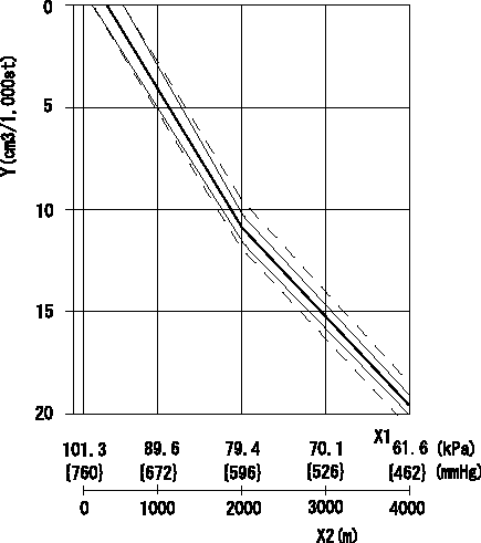
Full load injection quantity at high altitudes and ACS adjusting method
1. Full load injection quantity adjustment
(1)Remove the ACS cover and remove the bellows and adjusting shim.
(2)Perform all adjustments as per the adjustment standard except for ACS adjustment.
2. ACS adjustment
(1)Assemble the ACS cover, bellows and adjusting shim.
(2)At pump speed N1, adjust using a shim to obtain the decrease for the altitude shown in the table.
X1 = atmospheric pressure
X2 = altitude
Y = decrease quantity
(A) = adjustment value
(B) = test value
----------
N1=1100r/min
----------
----------
N1=1100r/min
----------
0000001801 CONTROL LEVER ANGLE

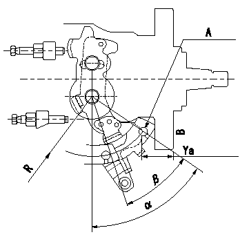
Control lever angle measurement
Apply 104740-9790.
1. Measure dimension Ya between the end of the lever and the flange face.
2. Measure the lever angle from the pin hole R (plate).
A = lever angle measuring position
B = flange face
----------
Ya=23.7~28.3mm R=49mm
----------
Ya=23.7~28.3mm R=49mm Alpha=50~58deg
----------
Ya=23.7~28.3mm R=49mm
----------
Ya=23.7~28.3mm R=49mm Alpha=50~58deg
0000001901 CONTROL LEVER ANGLE

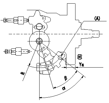
Control lever angle measurement
Apply 104740-7220.
1. Measure dimension L between the end of the lever and the flange face.
2. Measure the lever angle from the pin hole R (plate).
(A) = lever angle measuring position
(B) = flange face
----------
L=10.7~14.2mm R=49mm
----------
L=10.7~14.2mm R=49mm Alpha=50~58deg
----------
L=10.7~14.2mm R=49mm
----------
L=10.7~14.2mm R=49mm Alpha=50~58deg
Information:
Specifications
The following table lists the specifications for the CPU that is used on the 203-7810 Engine Monitoring Control Group and the 203-7811 Engine Monitoring Control Group.
Table 1
Item Description
Socket 7 Processor Intel Pentium MMX 233 MHz
BIOS Phoenix OEM BIOS
256 K X 8 flash EPROM (boot ROM)
Main Memory Up to 256 Mbytes DRAM (one 168 pin DIMM socket)
60 ns 3.3 V EDO / SDRAM with ECC
60 and 66 MHz bus speeds
L2 Cache Memory 512 KB pipeline burst static RAM
Chipsets Acer M1531B North Bridge
Acer M1543B South Bridge
Video Interface Chips & Technologies CHIPS 65550
2 Mbytes VGA local memory
Internal LVDS interface to indicator panel
External HD15 CRT (analog monitor) connector
Ethernet PCI 10/100 BaseT
Intel 82559 MAC
Filtered RJ-45 connector
Other CPU I/O Two RS232 serial ports ("COM1" and "COM2") (1)
Parallel port ("LPT1")
Two PS/2 ports for keyboard and mouse connections
Two USB ports
System Hardware Monitor LM78 Monitor IC mapped to IRQ5, drives diagnostics indicator
Internal temperature via DS1620 IC
User configured via BIOS
Other Features M5819 Real Time Clock chip with 256 bytes RAM
MAX705 Watchdog Timer
( 1 ) "COM2" is used by optional touchscreen interfaceSystem Hardware Monitor
The systems hardware monitor checks the following items:
2.8 V supply (CPU core)
3.3 V supply
5 V supply
12 V supply
Have questions with 104740-9790?
Group cross 104740-9790 ZEXEL
Nissan-Diesel
Nissan-Diesel
Nissan-Diesel
Samsung-Japan
Nissan-Diesel
104740-9790
9 460 614 337
1670021T02
INJECTION-PUMP ASSEMBLY
TD25
TD25