Information injection-pump assembly
ZEXEL
104740-9720
1047409720

Rating:
Cross reference number
ZEXEL
104740-9720
1047409720
Zexel num
Bosch num
Firm num
Name
Calibration Data:
Adjustment conditions
Test oil
1404 Test oil ISO4113orSAEJ967d
1404 Test oil ISO4113orSAEJ967d
Test oil temperature
degC
45
45
50
Nozzle
105000-2010
Bosch type code
NP-DN12SD12TT
Nozzle holder
105780-2080
Opening pressure
MPa
14.7
14.7
15.19
Opening pressure
kgf/cm2
150
150
155
Injection pipe
Inside diameter - outside diameter - length (mm) mm 2-6-840
Inside diameter - outside diameter - length (mm) mm 2-6-840
Transfer pump pressure
kPa
20
20
20
Transfer pump pressure
kgf/cm2
0.2
0.2
0.2
Direction of rotation (viewed from drive side)
Right R
Right R
(Solenoid timer adjustment condition)
OFF
Injection timing adjustment
Pump speed
r/min
1100
1100
1100
Average injection quantity
mm3/st.
52
51.5
52.5
Difference in delivery
mm3/st.
3
Basic
*
Oil temperature
degC
50
48
52
Injection timing adjustment_02
Pump speed
r/min
600
600
600
Average injection quantity
mm3/st.
51.1
50.1
52.1
Oil temperature
degC
50
48
52
Injection timing adjustment_03
Pump speed
r/min
1100
1100
1100
Average injection quantity
mm3/st.
52
51
53
Difference in delivery
mm3/st.
3.5
Basic
*
Oil temperature
degC
50
48
52
Injection timing adjustment_04
Pump speed
r/min
2150
2150
2150
Average injection quantity
mm3/st.
44.2
42.1
46.3
Oil temperature
degC
52
50
54
Injection timing adjustment_05
Pump speed
r/min
2350
2350
2350
Average injection quantity
mm3/st.
33.6
30.6
36.6
Basic
*
Oil temperature
degC
52
50
54
Injection quantity adjustment
Pump speed
r/min
2350
2350
2350
Average injection quantity
mm3/st.
33.6
31.6
35.6
Basic
*
Oil temperature
degC
52
50
54
Injection quantity adjustment_02
Pump speed
r/min
2700
2700
2700
Average injection quantity
mm3/st.
5
Oil temperature
degC
55
52
58
Injection quantity adjustment_03
Pump speed
r/min
2550
2550
2550
Average injection quantity
mm3/st.
10.8
7.3
14.3
Oil temperature
degC
55
52
58
Governor adjustment
Pump speed
r/min
350
350
350
Average injection quantity
mm3/st.
6.5
4.5
8.5
Difference in delivery
mm3/st.
2
Basic
*
Oil temperature
degC
48
46
50
Governor adjustment_02
Pump speed
r/min
350
350
350
Average injection quantity
mm3/st.
6.5
4
9
Difference in delivery
mm3/st.
2.5
Basic
*
Oil temperature
degC
48
46
50
Timer adjustment
Pump speed
r/min
100
100
100
Average injection quantity
mm3/st.
60
45
80
Basic
*
Oil temperature
degC
48
46
50
Remarks
Full
Full
Timer adjustment_02
Pump speed
r/min
100
100
100
Average injection quantity
mm3/st.
60
45
80
Oil temperature
degC
48
46
50
Speed control lever angle
Pump speed
r/min
350
350
350
Average injection quantity
mm3/st.
0
0
0
Oil temperature
degC
48
46
50
Remarks
Magnet OFF at idling position
Magnet OFF at idling position
0000000901
Pump speed
r/min
1100
1100
1100
Overflow quantity with S/T ON
cm3/min
390
260
520
Oil temperature
degC
50
48
52
_02
Pump speed
r/min
1100
1100
1100
Overflow quantity with S/T ON
cm3/min
490
360
620
Oil temperature
degC
50
48
52
Remarks
Without an O-ring
Without an O-ring
Stop lever angle
Pump speed
r/min
1100
1100
1100
Pressure with S/T ON
kPa
481
442
520
Pressure with S/T ON
kgf/cm2
4.9
4.5
5.3
Pressure with S/T OFF
kPa
373
344
402
Pressure with S/T OFF
kgf/cm2
3.8
3.5
4.1
Basic
*
Oil temperature
degC
50
48
52
Stop lever angle_02
Pump speed
r/min
1100
1100
1100
Pressure with S/T OFF
kPa
373
334
412
Pressure with S/T OFF
kgf/cm2
3.8
3.4
4.2
Basic
*
Oil temperature
degC
50
48
52
Stop lever angle_03
Pump speed
r/min
1700
1700
1700
Pressure with S/T OFF
kPa
510
471
549
Pressure with S/T OFF
kgf/cm2
5.2
4.8
5.6
Oil temperature
degC
50
48
52
0000001101
Pump speed
r/min
1100
1100
1100
Timer stroke with S/T ON
mm
4.3
3.9
4.7
Timer stroke with S/T OFF
mm
2.6
2.4
2.8
Basic
*
Oil temperature
degC
50
48
52
_02
Pump speed
r/min
700
700
700
Timer stroke with S/T OFF
mm
0.5
0.5
Oil temperature
degC
50
48
52
_03
Pump speed
r/min
1100
1100
1100
Timer stroke with S/T ON
mm
4.3
3.8
4.8
Timer stroke with S/T OFF
mm
2.6
2.3
2.9
Basic
*
Oil temperature
degC
50
48
52
_04
Pump speed
r/min
1700
1700
1700
Timer stroke with S/T OFF
mm
4.9
4.4
5.4
Oil temperature
degC
50
48
52
_05
Pump speed
r/min
2550
2550
2550
Timer stroke with S/T OFF
mm
7.4
6.9
7.8
Oil temperature
degC
55
52
58
0000001201
Max. applied voltage
V
8
8
8
Test voltage
V
13
12
14
Timing setting
K dimension
mm
3.3
3.2
3.4
KF dimension
mm
5.8
5.7
5.9
MS dimension
mm
1
0.9
1.1
Control lever angle alpha
deg.
25
23
27
Control lever angle beta
deg.
36
31
41
Test data Ex:
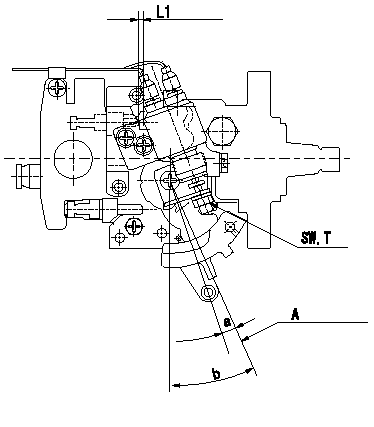
0000001801 ACCELERATOR SWITCH ADJ

Adjustment of the accelerator switch
ON - OFF changeover point: from idle to c (shim thickness L1 mm)
Idle-d: ON
e-full: OFF
A = idle lever position
----------
c=8+-2deg d=8deg e=8deg L1=5.2+-0.13mm
----------
SW=SW10 T=6~9N-m(0.6~0.9kgf-m) a=8+-2deg b=(25+-2deg) L1=(5.2mm)
----------
c=8+-2deg d=8deg e=8deg L1=5.2+-0.13mm
----------
SW=SW10 T=6~9N-m(0.6~0.9kgf-m) a=8+-2deg b=(25+-2deg) L1=(5.2mm)
Information:
Illustration 1 g00670863
CCM Cable requirements for Direct Connection to PC with 25 Pin Connector (1) PC with 25 pin RS-232C connector (2) 25 to 25 pin female to male cable (3) Null modem adapter (4) CCM with 25 pin RS-232C connectorIf the PC has a 9 pin RS-232C connector a 9 to 25 pin cable with a null modem adapter is required. Refer to Illustration 2.
Illustration 2 g00670882
CCM Cable Requirements for Direct Connection to PC with 9-Pin Connector (1) PC with 9 pin RS-232C connector (2) 9 to 25 pin cable (3) Null modem adapter (4) CCM with 25 pin RS-232C connectorThe null modem adapter connects the Data Transmit of one device to the Data Receive of the other device. The Null Modem adapter connects the Data Carrier Detect and the Data Terminal Ready pins in a similar manner. Cables are available from most personal computer suppliers.Note: Verify that the cables and null modem adapters are compatible with the specifications in Tables 1 and 2.
Table 1
25 PIN RS-232C PIN DEFINITIONS
Pin Number Description
2 Data Transmit (TX)
3 Data Receive (RX)
7 Ground
8 Data Carrier Detect (DCD)
20 Data Terminal Ready (DTR)
Table 2
9 PIN RS-232C PIN DEFINITIONS
Pin Number Description
1 Data Carrier Detect (DCD)
2 Data Receive (RX
3 Data Transmit (TX)
4 Data Terminal Ready (DTR)
5 Ground A 25 to 25 pin cable or a 9 to 25 pin cable is needed when the CCM is used with a modem. Refer to Illustrations 3 and 4. The type of cable will depend on the number of pins on the RS-232C connector of the PC.Note: Do not use a null modem adapter to connect a modem to the PC or the CCM.
Illustration 3 g00645279
CCM Cable Requirements for Modem Connection to PC with 9-Pin Connector (1) PC with 9 pin RS-232C connector (2) 9 to 25 pin cable (3) Modems that are connected by telephone lines (4) 25 to 25 pin cable (5) CCM with 25 pin RS-232C connector (6) Telephone line
Illustration 4 g00645341
CCM Cable Requirements for Modem Connection to PC with 25-Pin Connector (1) PC with 25 pin RS-232C connector (2) 25 to 25 pin cable (3) Modems that are connected by telephone lines (4) 25 to 25 pin cable (5) CCM with 25 pin RS-232C connector (6) Telephone line