Information injection-pump assembly
ZEXEL
104740-9690
1047409690

Rating:
Cross reference number
ZEXEL
104740-9690
1047409690
Zexel num
Bosch num
Firm num
Name
Calibration Data:
Adjustment conditions
Test oil
1404 Test oil ISO4113orSAEJ967d
1404 Test oil ISO4113orSAEJ967d
Test oil temperature
degC
45
45
50
Nozzle
105000-2010
Bosch type code
NP-DN12SD12TT
Nozzle holder
105780-2080
Opening pressure
MPa
14.7
14.7
15.19
Opening pressure
kgf/cm2
150
150
155
Injection pipe
Inside diameter - outside diameter - length (mm) mm 2-6-840
Inside diameter - outside diameter - length (mm) mm 2-6-840
Transfer pump pressure
kPa
20
20
20
Transfer pump pressure
kgf/cm2
0.2
0.2
0.2
Direction of rotation (viewed from drive side)
Right R
Right R
Injection timing adjustment
Pump speed
r/min
1100
1100
1100
Average injection quantity
mm3/st.
52
51.5
52.5
Difference in delivery
mm3/st.
3
Basic
*
Oil temperature
degC
50
48
52
Injection timing adjustment_02
Pump speed
r/min
600
600
600
Average injection quantity
mm3/st.
51.1
49.1
53.1
Oil temperature
degC
50
48
52
Injection timing adjustment_03
Pump speed
r/min
1100
1100
1100
Average injection quantity
mm3/st.
52
51
53
Difference in delivery
mm3/st.
3.5
Basic
*
Oil temperature
degC
50
48
52
Injection timing adjustment_04
Pump speed
r/min
2150
2150
2150
Average injection quantity
mm3/st.
44.2
42.1
46.3
Oil temperature
degC
52
50
54
Injection timing adjustment_05
Pump speed
r/min
2350
2350
2350
Average injection quantity
mm3/st.
33.6
30.6
36.6
Basic
*
Oil temperature
degC
52
50
54
Injection quantity adjustment
Pump speed
r/min
2350
2350
2350
Average injection quantity
mm3/st.
33.6
31.6
35.6
Basic
*
Oil temperature
degC
52
50
54
Injection quantity adjustment_02
Pump speed
r/min
2550
2550
2550
Average injection quantity
mm3/st.
10.8
7.3
14.3
Oil temperature
degC
55
52
58
Injection quantity adjustment_03
Pump speed
r/min
2700
2700
2700
Average injection quantity
mm3/st.
5
Oil temperature
degC
55
52
58
Governor adjustment
Pump speed
r/min
350
350
350
Average injection quantity
mm3/st.
6.5
4.5
8.5
Difference in delivery
mm3/st.
2
Basic
*
Oil temperature
degC
48
46
50
Governor adjustment_02
Pump speed
r/min
350
350
350
Average injection quantity
mm3/st.
6.5
4
9
Difference in delivery
mm3/st.
2.5
Basic
*
Oil temperature
degC
48
46
50
Timer adjustment
Pump speed
r/min
100
100
100
Average injection quantity
mm3/st.
60
45
80
Oil temperature
degC
48
46
50
Remarks
Full
Full
Timer adjustment_02
Pump speed
r/min
100
100
100
Average injection quantity
mm3/st.
60
45
80
Oil temperature
degC
48
46
50
Speed control lever angle
Pump speed
r/min
350
350
350
Average injection quantity
mm3/st.
0
0
0
Oil temperature
degC
48
46
50
Remarks
Magnet OFF at idling position
Magnet OFF at idling position
0000000901
Pump speed
r/min
1100
1100
1100
Overflow quantity
cm3/min
390
260
520
Oil temperature
degC
50
48
52
Stop lever angle
Pump speed
r/min
1100
1100
1100
Pressure
kPa
431
402
460
Pressure
kgf/cm2
4.4
4.1
4.7
Basic
*
Oil temperature
degC
50
48
52
Stop lever angle_02
Pump speed
r/min
1100
1100
1100
Pressure
kPa
431
392
470
Pressure
kgf/cm2
4.4
4
4.8
Basic
*
Oil temperature
degC
50
48
52
Stop lever angle_03
Pump speed
r/min
1700
1700
1700
Pressure
kPa
579
540
618
Pressure
kgf/cm2
5.9
5.5
6.3
Oil temperature
degC
50
48
52
0000001101
Pump speed
r/min
1100
1100
1100
Timer stroke
mm
2.5
2.3
2.7
Basic
*
Oil temperature
degC
50
48
52
_02
Pump speed
r/min
700
700
700
Timer stroke
mm
0.5
0.5
Oil temperature
degC
50
48
52
_03
Pump speed
r/min
1100
1100
1100
Timer stroke
mm
2.5
2.2
2.8
Basic
*
Oil temperature
degC
50
48
52
_04
Pump speed
r/min
1700
1700
1700
Timer stroke
mm
4.6
4.1
5.1
Oil temperature
degC
50
48
52
_05
Pump speed
r/min
2550
2550
2550
Timer stroke
mm
7.4
6.9
7.8
Oil temperature
degC
55
52
58
0000001201
Max. applied voltage
V
8
8
8
Test voltage
V
13
12
14
Timing setting
K dimension
mm
3.3
3.2
3.4
KF dimension
mm
5.8
5.7
5.9
MS dimension
mm
1
0.9
1.1
Control lever angle alpha
deg.
25
23
27
Control lever angle beta
deg.
36
31
41
Test data Ex:
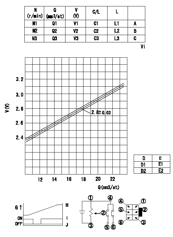
0000001801 POTENTIOMETER ADJUSTMENT

Adjustment of the potentiometer
1. Measure the injection quantity at pump speed N2 and with the control lever C2 from idle (gap L2). Then determine the voltage from the formula and adjust the potentiometer.
Voltage conversion formula: V+-0.03 = 0.068Q+1.59
2. At the full lever position, confirm at least V4.
N:Pump speed
Q:Injection quantity
V:Output voltage
C/L: control lever position
L:Thickness of the shim
A:-
B:Adjusting point
C:-
Vi:Applied voltage
D:Conversion point
D1:ON-->OFF
D2:OFF-->ON
E:Lever opening (from idle)
F:Connecting diagram for the potentiometer
G:Output
H:Output when (2) and (3) connected.
I:When (4) or (6) connected: switch OFF to ON.
J:When (4) or (5) connected: switch ON to OFF.
----------
N2=750r/min C2=11.5deg L2=7.6mm V4=6V
----------
N1=500r/min N2=750r/min N3=1100r/min V1=2.13V V2=2.8V V3=3.13V Q1=(11.0+-2.7mm3/st) Q2=17.8+-1.0mm3/st Q3=(17.2+-4.7mm3/st) C1=(7.5deg) C2=(11.5deg) C3=(13.5deg) L1=(5.0mm) L2=(7.6mm) L3=(9.0mm) E1=4.7+-3.5deg E2=23.7+-3.5deg Vi=10V
----------
N2=750r/min C2=11.5deg L2=7.6mm V4=6V
----------
N1=500r/min N2=750r/min N3=1100r/min V1=2.13V V2=2.8V V3=3.13V Q1=(11.0+-2.7mm3/st) Q2=17.8+-1.0mm3/st Q3=(17.2+-4.7mm3/st) C1=(7.5deg) C2=(11.5deg) C3=(13.5deg) L1=(5.0mm) L2=(7.6mm) L3=(9.0mm) E1=4.7+-3.5deg E2=23.7+-3.5deg Vi=10V
Information:
Remote Fault Reset$00 $0D aUsed to reset faults on the CCM.
Table 2
(a) $00 - $7F = Retain current CCM inactive fault status.
$80 - $FF = Reset CCM inactive fault. Device ID Code$00 $80 aabbccUsed to read the device ID code from the CCM as well as other components on the data link. Each pair of bytes (aa, bb, cc) is sent LSB first.
Table 3
(aa) Module ID: will always equal $61, data will be sent as $61 $00
(bb) Service Tool Support Change Level: $01, data will be sent as $01 $00
(cc) Application type:$FF $E0, data will be sent as $E0 $FF CCM Error Codes$00 $82 abUsed to read the CCM Error Codes.
Table 4
(a) bit 1 = Reserved
(b) (1) Fault Code Status
bit 8 1 = RS-232C link message fault exists
bit 7 1 = Miscellaneous Cat Data Link fault
bit 6 1 = Invalid Cat Data message fault
bit 5 1 = Internal buffer overflow on RS-232C or Data Data Link fault
bit 4 1 = RS-232C short circuit fault
bit 3 1 = Memory battery is weak
bit 2 1 = M5X message error (checksum or byte count error)
bit 1 1 = EEPROM fault
( 1 ) A value of 0 (zero) in bits 1 through 8 indicates that particular fault does not exist.CCM Communication Rate Change Enable$AA $12 aUsed to determine if the CCM is connected to the host computer directly or remotely using a modem. Also used to enable or disable the host computers ability to change the communication rate of the RS-232C serial port.
Table 5
(a) Bit 4 Reserved for Caterpillar.
Bit 3 0 = Enable password protection
1 = Disable password protection
Bit 2 0 = Enable baud rate change
1 = Disable baud rate change
Bit 1 0 = Direct connection
1 = Modem connection Access Level 1 Password$AA $87 aaaaaaaaUsed to read or program the Level 1 Password
Table 6
(aaaaaaaa) Level 1 password in printable ASCII form. Must be at least 6, but no more than