Information injection-pump assembly
ZEXEL
104740-9682
1047409682

Rating:
Cross reference number
ZEXEL
104740-9682
1047409682
Zexel num
Bosch num
Firm num
Name
104740-9682
INJECTION-PUMP ASSEMBLY
Calibration Data:
Adjustment conditions
Test oil
1404 Test oil ISO4113orSAEJ967d
1404 Test oil ISO4113orSAEJ967d
Test oil temperature
degC
45
45
50
Nozzle
105000-2010
Bosch type code
NP-DN12SD12TT
Nozzle holder
105780-2080
Opening pressure
MPa
14.7
14.7
15.19
Opening pressure
kgf/cm2
150
150
155
Injection pipe
Inside diameter - outside diameter - length (mm) mm 2-6-840
Inside diameter - outside diameter - length (mm) mm 2-6-840
Transfer pump pressure
kPa
20
20
20
Transfer pump pressure
kgf/cm2
0.2
0.2
0.2
Direction of rotation (viewed from drive side)
Right R
Right R
(Solenoid timer adjustment condition)
OFF
Injection timing adjustment
Pump speed
r/min
1100
1100
1100
Average injection quantity
mm3/st.
52.2
51.7
52.7
Difference in delivery
mm3/st.
3
Basic
*
Injection timing adjustment_02
Pump speed
r/min
2550
2550
2550
Average injection quantity
mm3/st.
10.1
5.6
14.6
Injection timing adjustment_03
Pump speed
r/min
2350
2350
2350
Average injection quantity
mm3/st.
33
30.5
35.5
Injection timing adjustment_04
Pump speed
r/min
2150
2150
2150
Average injection quantity
mm3/st.
42.9
40.8
45
Injection timing adjustment_05
Pump speed
r/min
1100
1100
1100
Average injection quantity
mm3/st.
52.2
51.2
53.2
Injection timing adjustment_06
Pump speed
r/min
600
600
600
Average injection quantity
mm3/st.
52.8
50.8
54.8
Injection quantity adjustment
Pump speed
r/min
2350
2350
2350
Average injection quantity
mm3/st.
33
31
35
Basic
*
Injection quantity adjustment_02
Pump speed
r/min
2700
2700
2700
Average injection quantity
mm3/st.
5
Governor adjustment
Pump speed
r/min
400
400
400
Average injection quantity
mm3/st.
7.3
5.3
9.3
Difference in delivery
mm3/st.
2
Basic
*
Governor adjustment_02
Pump speed
r/min
400
400
400
Average injection quantity
mm3/st.
7.3
5.3
9.3
Governor adjustment_03
Pump speed
r/min
500
500
500
Average injection quantity
mm3/st.
3
Timer adjustment
Pump speed
r/min
100
100
100
Average injection quantity
mm3/st.
62.5
45
80
Basic
*
Speed control lever angle
Pump speed
r/min
400
400
400
Average injection quantity
mm3/st.
0
0
0
Remarks
Magnet OFF
Magnet OFF
0000000901
Pump speed
r/min
1100
1100
1100
Overflow quantity
cm3/min
390
258
522
_02
Pump speed
r/min
1100
1100
1100
Overflow quantity
cm3/min
489
360
618
Remarks
Without an O-ring
Without an O-ring
Stop lever angle
Pump speed
r/min
750
750
750
Pressure with S/T ON
kPa
402
363
441
Pressure with S/T ON
kgf/cm2
4.1
3.7
4.5
Pressure with S/T OFF
kPa
294.5
275
314
Pressure with S/T OFF
kgf/cm2
3
2.8
3.2
Basic
*
Stop lever angle_02
Pump speed
r/min
750
750
750
Pressure with S/T ON
kPa
402
363
441
Pressure with S/T ON
kgf/cm2
4.1
3.7
4.5
Pressure with S/T OFF
kPa
294.5
275
314
Pressure with S/T OFF
kgf/cm2
3
2.8
3.2
Stop lever angle_03
Pump speed
r/min
1100
1100
1100
Pressure with S/T OFF
kPa
372.5
343
402
Pressure with S/T OFF
kgf/cm2
3.8
3.5
4.1
Stop lever angle_04
Pump speed
r/min
1700
1700
1700
Pressure with S/T OFF
kPa
510
481
539
Pressure with S/T OFF
kgf/cm2
5.2
4.9
5.5
Stop lever angle_05
Pump speed
r/min
2150
2150
2150
Pressure with S/T OFF
kPa
598.5
569
628
Pressure with S/T OFF
kgf/cm2
6.1
5.8
6.4
0000001101
Pump speed
r/min
750
750
750
Timer stroke with S/T ON
mm
2.8
2.4
3.2
Timer stroke with S/T OFF
mm
1.2
1
1.4
Basic
*
_02
Pump speed
r/min
750
750
750
Timer stroke with S/T ON
mm
2.8
2.3
3.3
Timer stroke with S/T OFF
mm
1.2
0.9
1.5
_03
Pump speed
r/min
1100
1100
1100
Timer stroke with S/T OFF
mm
2.5
1.9
3.1
_04
Pump speed
r/min
1700
1700
1700
Timer stroke with S/T OFF
mm
4.9
4.2
5.6
_05
Pump speed
r/min
2550
2550
2550
Timer stroke with S/T OFF
mm
7.3
6.8
7.8
0000001201
Max. applied voltage
V
8
8
8
Test voltage
V
13
12
14
Timing setting
K dimension
mm
3.3
3.2
3.4
KF dimension
mm
5.8
5.7
5.9
MS dimension
mm
0.9
0.8
1
Control lever angle alpha
deg.
55.5
51.5
59.5
Control lever angle beta
deg.
36
31
41
Test data Ex:
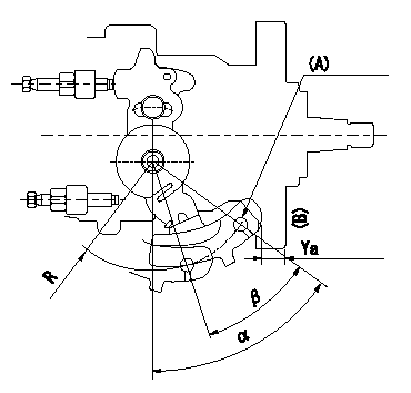
0000001801 CONTROL LEVER ANGLE

Control lever angle measurement
1. Measure dimension Ya between the end of the lever and the flange face B.
2. Measure the lever angle from the R (plate) pin hole.
(A) Lever angle measurement position
----------
Ya=8.4~12.2mm R=53mm
----------
Ya=8.4~12.2mm R=53mm Alpha=51.5~59.5deg Beta=31~41deg
----------
Ya=8.4~12.2mm R=53mm
----------
Ya=8.4~12.2mm R=53mm Alpha=51.5~59.5deg Beta=31~41deg
0000001901 POTENTIOMETER ADJUSTMENT

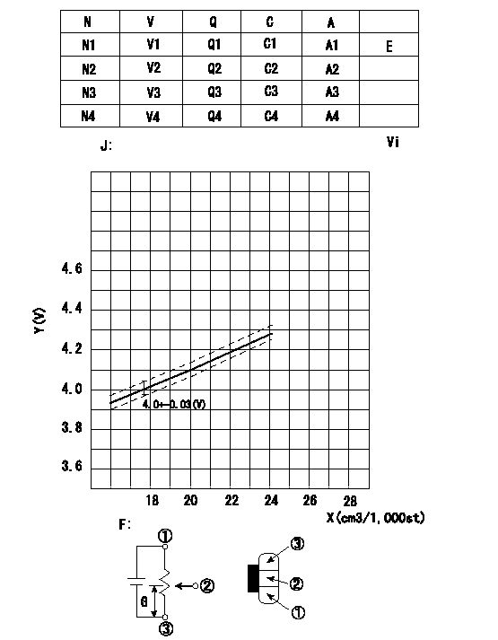
Adjustment of the potentiometer
Measure the injection quantity with the control lever a from the idle position (equal to shim thickness L1) at pump speed N5. Install the potentiometer so that injection quantity and output voltage correspond as shown in the graph.
J = formula
A = shim thickness
C = control lever angle
E = adjusting point
Vi = applied voltage
V = potentiometer voltage
X = injection quantity Q
Y = voltage (V)
C2 = idle
C3 = full speed
F = potentiometer circuit diagram
G = output
N = pump speed
Q = injection quantity
1 = black
2 = blue yellow
3 = blue red
----------
N5=750r/min a=9.0deg L1=6.0mm
----------
N1=750r/min N2=-r/min N3=-r/min N4=-r/min V1=4.0V V2=-V V3=-V V4=-V Q1=17.8+-1.8cm3/1,000st Q2=-cm3/1,000st Q3=-cm3/1,000st Q4=-cm3/1,000st C1=(9.0)deg C2=- C3=- C4=- A1=(6.0)mm A2=- A3=- A4=- J=V+-0.03=0.045X+3.197
----------
N5=750r/min a=9.0deg L1=6.0mm
----------
N1=750r/min N2=-r/min N3=-r/min N4=-r/min V1=4.0V V2=-V V3=-V V4=-V Q1=17.8+-1.8cm3/1,000st Q2=-cm3/1,000st Q3=-cm3/1,000st Q4=-cm3/1,000st C1=(9.0)deg C2=- C3=- C4=- A1=(6.0)mm A2=- A3=- A4=- J=V+-0.03=0.045X+3.197
Information:
Illustration 1 g00656709
(1) Error code (2) Activity on CAT Data Link (3) First digit of error code (4) The CCM is transmitting on RS 232C. (5) Second digit of error code (6) The CCM is receiving data on the RS 232C.The values E, 0, and 0 indicate an error code of 00. The code E00 means that no faults are present, and the CCM is in normal operating mode. The complete list of error codes are in the Operation and Maintenance Manual, "Troubleshooting" section. The periods on the display will flash when information is transmitted on the CAT Data Link. The periods on the display will flash when information is transmitted on the RS-232C port. No period indicates that no activity is taking place.Note: Units with the part number 117-6170 Customer Communication Module will display the faults that have been logged. Each fault will be displayed for 2 seconds in 60 second intervals. This flashing fault log will not appear for any other version of CCM. The fault log can be cleared by using the PC software for the CCM.CCM Power Up Display
The CCM display will perform a lamp test (8.8.8.). The parameters for communication protocol (n81 9600 E00) will be displayed next. An example of the power up sequence is given below:
Table 1
8.8.8. n81 9600 E00
8.8.8. All of the segments are turned on for a two second lamp test.
n81
n
8
1 No parity (default value)
Eight data bits (default value)
One stop bit (default value)
9600 Rate of Communication (default value)
E00 Error Code
No faults are present. The values for communication can be changed by using a host device or by using the PC software for the CCM. Refer to "Caterpillar CCM PC For Windows: Getting Started Manual". The values for communication must match the values for the modems (if used) and the values for the host device.
Have questions with 104740-9682?
Group cross 104740-9682 ZEXEL
Nissan-Diesel
104740-9682
INJECTION-PUMP ASSEMBLY