Information injection-pump assembly
ZEXEL
104740-9620
1047409620
NISSAN-DIESEL
1670044G00
1670044g00

Rating:
Cross reference number
ZEXEL
104740-9620
1047409620
NISSAN-DIESEL
1670044G00
1670044g00
Zexel num
Bosch num
Firm num
Name
Calibration Data:
Adjustment conditions
Test oil
1404 Test oil ISO4113orSAEJ967d
1404 Test oil ISO4113orSAEJ967d
Test oil temperature
degC
45
45
50
Nozzle
105000-2010
Bosch type code
NP-DN12SD12TT
Nozzle holder
105780-2080
Opening pressure
MPa
14.7
14.7
15.19
Opening pressure
kgf/cm2
150
150
155
Injection pipe
Inside diameter - outside diameter - length (mm) mm 2-6-840
Inside diameter - outside diameter - length (mm) mm 2-6-840
Transfer pump pressure
kPa
20
20
20
Transfer pump pressure
kgf/cm2
0.2
0.2
0.2
Direction of rotation (viewed from drive side)
Right R
Right R
Injection timing adjustment
Pump speed
r/min
1100
1100
1100
Average injection quantity
mm3/st.
48.5
48
49
Difference in delivery
mm3/st.
3
Basic
*
Injection timing adjustment_02
Pump speed
r/min
2500
2500
2500
Average injection quantity
mm3/st.
12.1
9.6
14.6
Injection timing adjustment_03
Pump speed
r/min
2300
2300
2300
Average injection quantity
mm3/st.
32.8
28.3
37.3
Injection timing adjustment_04
Pump speed
r/min
2150
2150
2150
Average injection quantity
mm3/st.
40.6
38.5
42.7
Injection timing adjustment_05
Pump speed
r/min
1100
1100
1100
Average injection quantity
mm3/st.
48.5
47.5
49.5
Injection timing adjustment_06
Pump speed
r/min
600
600
600
Average injection quantity
mm3/st.
47.1
45.1
49.1
Injection quantity adjustment
Pump speed
r/min
2500
2500
2500
Average injection quantity
mm3/st.
12.1
10.1
14.1
Basic
*
Injection quantity adjustment_02
Pump speed
r/min
2700
2700
2700
Average injection quantity
mm3/st.
5
Governor adjustment
Pump speed
r/min
350
350
350
Average injection quantity
mm3/st.
6.5
4.5
8.5
Difference in delivery
mm3/st.
2
Basic
*
Governor adjustment_02
Pump speed
r/min
350
350
350
Average injection quantity
mm3/st.
6.5
4.5
8.5
Governor adjustment_03
Pump speed
r/min
450
450
450
Average injection quantity
mm3/st.
2
Timer adjustment
Pump speed
r/min
100
100
100
Average injection quantity
mm3/st.
62.5
45
80
Basic
*
Speed control lever angle
Pump speed
r/min
350
350
350
Average injection quantity
mm3/st.
0
0
0
Remarks
Magnet OFF
Magnet OFF
0000000901
Pump speed
r/min
1100
1100
1100
Overflow quantity
cm3/min
390
258
522
Stop lever angle
Pump speed
r/min
1700
1700
1700
Pressure
kPa
578.5
549
608
Pressure
kgf/cm2
5.9
5.6
6.2
Basic
*
Stop lever angle_02
Pump speed
r/min
1700
1700
1700
Pressure
kPa
578.5
549
608
Pressure
kgf/cm2
5.9
5.6
6.2
Stop lever angle_03
Pump speed
r/min
2150
2150
2150
Pressure
kPa
676.5
647
706
Pressure
kgf/cm2
6.9
6.6
7.2
0000001101
Pump speed
r/min
1700
1700
1700
Timer stroke
mm
4.9
4.7
5.1
Basic
*
_02
Pump speed
r/min
1100
1100
1100
Timer stroke
mm
2.6
2.2
3
_03
Pump speed
r/min
1700
1700
1700
Timer stroke
mm
4.9
4.6
5.2
_04
Pump speed
r/min
2150
2150
2150
Timer stroke
mm
6.6
6
7.2
_05
Pump speed
r/min
2500
2500
2500
Timer stroke
mm
7.8
6.8
8.8
0000001201
Max. applied voltage
V
8
8
8
Test voltage
V
13
12
14
Timing setting
K dimension
mm
3.3
3.2
3.4
KF dimension
mm
5.8
5.7
5.9
MS dimension
mm
1
0.9
1.1
Control lever angle alpha
deg.
55.5
51.5
59.5
Control lever angle beta
deg.
36
31
41
Test data Ex:
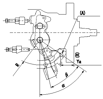
0000001801 CONTROL LEVER ANGLE

Control lever angle measurement
1. Measure dimension Ya between the end of the lever and the flange face.
2. Measure the lever angle from the pin hole R (plate).
(A) = lever angle and lever reaction force measuring position
----------
Ya=24.3~28.7mm R=53mm
----------
Ya=24.3~28.7mm R=53mm Alpha=51.5~59.5deg Beta=31~41deg
----------
Ya=24.3~28.7mm R=53mm
----------
Ya=24.3~28.7mm R=53mm Alpha=51.5~59.5deg Beta=31~41deg
Information:
Test Procedure
System Operation
The SLC 5/04 diagnostic indicators are located on the front of the following components: Power Supply, CPU and I/O Modules.The diagnostic indicators help trace the source of the fault. Faults can be found in the following components: Input devices, Output devices, Wiring and The controller.When the red "POWER" LED is illuminated and when the green "RUN" LED is illuminated, the processor is in normal operation.If the LED indicators are illuminated and an error exists, proceed to 1.
Illustration 1 g00562937
Functional Test
Check the electrical connectors and check the wiring.
Bodily contact with electrical potential can cause bodily injury or death.To avoid the possibility of injury or death, ensure that the main power supply has been disconnected before performing any maintenance or removing any modules.
Disconnect the power supply.
Check the electrical connectors and check the wiring for damage or bad connections.
Verify that all modules are properly seated.
Verify the status of the LED on the SLC 5/04.The results of the preceding procedure are in the following list:
All of the components are fully installed. All of the components are free of corrosion. All of the components are free of damage. All of the modules are properly seated. Proceed to 2.
The components are not fully installed. The components are not free of corrosion. The components are damaged. All of the modules are not properly seated. Repair the component. Verify that the repair resolves the problem. STOP.
Replace the processor.Reference: Troubleshooting, "Processor - Replace".The results of the preceding procedure are in the following list:
The error is corrected. Stop.
Errors are displayed on the LED indicators. Follow the procedures in the Troubleshooting, "Using LED Indicators to Troubleshoot Modules". Stop.