Information injection-pump assembly
ZEXEL
104740-9450
1047409450
NISSAN-DIESEL
1670011T21
1670011t21

Rating:
Cross reference number
ZEXEL
104740-9450
1047409450
NISSAN-DIESEL
1670011T21
1670011t21
Zexel num
Bosch num
Firm num
Name
Calibration Data:
Adjustment conditions
Test oil
1404 Test oil ISO4113orSAEJ967d
1404 Test oil ISO4113orSAEJ967d
Test oil temperature
degC
45
45
50
Nozzle
105000-2010
Bosch type code
NP-DN12SD12TT
Nozzle holder
105780-2080
Opening pressure
MPa
14.7
14.7
15.19
Opening pressure
kgf/cm2
150
150
155
Injection pipe
Inside diameter - outside diameter - length (mm) mm 2-6-840
Inside diameter - outside diameter - length (mm) mm 2-6-840
Transfer pump pressure
kPa
20
20
20
Transfer pump pressure
kgf/cm2
0.2
0.2
0.2
Direction of rotation (viewed from drive side)
Right R
Right R
(Solenoid timer adjustment condition)
OFF
Injection timing adjustment
Pump speed
r/min
1100
1100
1100
Average injection quantity
mm3/st.
52
51.5
52.5
Difference in delivery
mm3/st.
3
Basic
*
Oil temperature
degC
50
48
52
Injection timing adjustment_02
Pump speed
r/min
600
600
600
Average injection quantity
mm3/st.
51.1
49.1
53.1
Oil temperature
degC
50
48
52
Injection timing adjustment_03
Pump speed
r/min
1100
1100
1100
Average injection quantity
mm3/st.
52
51
53
Difference in delivery
mm3/st.
3.5
Basic
*
Oil temperature
degC
50
48
52
Injection timing adjustment_04
Pump speed
r/min
2150
2150
2150
Average injection quantity
mm3/st.
44.2
42.1
46.3
Oil temperature
degC
52
50
54
Injection quantity adjustment
Pump speed
r/min
2350
2350
2350
Average injection quantity
mm3/st.
33.6
31.6
35.6
Basic
*
Oil temperature
degC
52
50
54
Injection quantity adjustment_02
Pump speed
r/min
2350
2350
2350
Average injection quantity
mm3/st.
33.6
30.6
36.6
Basic
*
Oil temperature
degC
52
50
54
Injection quantity adjustment_03
Pump speed
r/min
2550
2550
2550
Average injection quantity
mm3/st.
10.8
7.3
14.3
Oil temperature
degC
55
52
58
Injection quantity adjustment_04
Pump speed
r/min
2700
2700
2700
Average injection quantity
mm3/st.
5
Oil temperature
degC
55
52
58
Governor adjustment
Pump speed
r/min
350
350
350
Average injection quantity
mm3/st.
6.5
4.5
8.5
Difference in delivery
mm3/st.
2
Basic
*
Oil temperature
degC
48
46
50
Governor adjustment_02
Pump speed
r/min
350
350
350
Average injection quantity
mm3/st.
6.5
4
9
Difference in delivery
mm3/st.
2.5
Oil temperature
degC
48
46
50
Timer adjustment
Pump speed
r/min
100
100
100
Average injection quantity
mm3/st.
60
45
80
Basic
*
Oil temperature
degC
48
46
50
Remarks
Full
Full
Timer adjustment_02
Pump speed
r/min
100
100
100
Average injection quantity
mm3/st.
60
45
80
Oil temperature
degC
48
46
50
Speed control lever angle
Pump speed
r/min
350
350
350
Average injection quantity
mm3/st.
0
0
0
Oil temperature
degC
48
46
50
Remarks
Magnet OFF at idling position
Magnet OFF at idling position
0000000901
Pump speed
r/min
1100
1100
1100
Overflow quantity with S/T ON
cm3/min
390
260
520
Oil temperature
degC
50
48
52
Stop lever angle
Pump speed
r/min
1700
1700
1700
Pressure with S/T OFF
kPa
510
481
539
Pressure with S/T OFF
kgf/cm2
5.2
4.9
5.5
Basic
*
Oil temperature
degC
50
48
52
Stop lever angle_02
Pump speed
r/min
1700
1700
1700
Pressure with S/T OFF
kPa
510
471
549
Pressure with S/T OFF
kgf/cm2
5.2
4.8
5.6
Basic
*
Oil temperature
degC
50
48
52
Stop lever angle_03
Pump speed
r/min
2150
2150
2150
Pressure with S/T OFF
kPa
608
569
647
Pressure with S/T OFF
kgf/cm2
6.2
5.8
6.6
Oil temperature
degC
52
50
54
0000001101
Pump speed
r/min
1700
1700
1700
Timer stroke with S/T OFF
mm
4.6
4.3
4.9
Basic
*
Oil temperature
degC
50
48
52
_02
Pump speed
r/min
700
700
700
Timer stroke with S/T OFF
mm
0.5
0.5
Oil temperature
degC
50
48
52
_03
Pump speed
r/min
1100
1100
1100
Timer stroke with S/T ON
mm
4.8
4.2
5.4
Timer stroke with S/T OFF
mm
2.5
1.9
3.1
Oil temperature
degC
50
48
52
_04
Pump speed
r/min
1700
1700
1700
Timer stroke with S/T OFF
mm
4.6
4.2
5
Basic
*
Oil temperature
degC
50
48
52
_05
Pump speed
r/min
2550
2550
2550
Timer stroke with S/T OFF
mm
7
6.5
7.4
Oil temperature
degC
55
52
58
0000001201
Max. applied voltage
V
16
16
16
Test voltage
V
25
24
26
Timing setting
K dimension
mm
3.3
3.2
3.4
KF dimension
mm
5.8
5.7
5.9
MS dimension
mm
1
0.9
1.1
Control lever angle alpha
deg.
25
23
27
Control lever angle beta
deg.
42
37
47
Test data Ex:
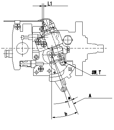
0000001801 ACCELERATOR SWITCH ADJ

Adjustment of the accelerator switch
ON - OFF changeover point: from idle to c (shim thickness L1 mm)
Idle-d: ON
e-full: OFF
A:Idling lever position
----------
c=8+-0.2deg d=8deg e=8deg L1=5.2+-0.13mm
----------
SW=SW10 T=6~9N-m(0.6~0.9kgf-m) a=8+-0.2deg b=25+-4deg L1=(5.2mm)
----------
c=8+-0.2deg d=8deg e=8deg L1=5.2+-0.13mm
----------
SW=SW10 T=6~9N-m(0.6~0.9kgf-m) a=8+-0.2deg b=25+-4deg L1=(5.2mm)
Information:
Illustration 1 g00564355
7W-2743 Electronic Speed Switch (ESS)
(1) Push button for Overspeed Verification
(2) Reset button
(3) Overspeed indicator lamp
(4) Seal screw plug for adjusting the engine overspeed
(5) Seal screw plug for adjusting the crank terminate speed
(6) Seal screw plug for adjusting the oil step pressure speed setting The overspeed calibration can increase the overspeed setting or the overspeed calibration can decrease the overspeed setting in order to shut down the engine when the overspeed verification button is pressed. The overspeed setting is correctly made when the engine is running at 75% of the overspeed setting. The engine then shuts down when the overspeed verification button is pressed.Use the following procedure in order to adjust the overspeed setting.
Remove the lockwire and the seal from seal screw plug (4). Remove seal screw plug (4) from the access hole for the overspeed adjustment screw.
Use a small screwdriver to lightly turn the overspeed adjustment screw in the direction of the "MAX" arrow or the clockwise direction. Turn the screw 20 times. The overspeed adjustment screw will vary the setting of a potentiometer that is inside of the ESS. The overspeed adjustment screw will not cause damage to the potentiometer. Also, the screw can not be removed if the screw is turned in the wrong direction.
Run the engine at 75% of the desired overspeed setting rpm. Refer to the Speed Specification Chart.
While the engine is running at 75% of the overspeed setting rpm, press "VERIFY" button (1). While the button is depressed, slowly turn the overspeed adjustment screw in the opposite direction of the "MAX" arrow or the counterclockwise direction until overspeed indicator lamp (3) is lighted. The engine will shut down if the ESS is connected to the fuel shutoff solenoid (FSOS) and the air shutoff solenoid, if equipped.
In order to reset the ESS, press "RESET" button (2). The air shutoff valve must be reset by hand, if equipped.
Slowly turn the overspeed adjustment screw in the clockwise direction for one turn. Repeat Steps 3, 4, and 5. More adjustment may be necessary in order to gain the correct setting. Turn the overspeed adjustment screw in the clockwise direction in order to increase the overspeed setting. Turn the overspeed adjustment screw in the counterclockwise direction in order to decrease the overspeed setting.
When the overspeed setting is correct, install seal screw plug (4) in the access hole for the overspeed adjustment screw. Tighten the screw to a torque of 0.20 0.03 N m (1.8 .3 lb in). Install the lockwire and the seal if the calibration of the crank termination speed and the oil step speed calibration are also complete.