Information injection-pump assembly
ZEXEL
104740-9330
1047409330
NISSAN-DIESEL
1670002N13
1670002n13

Rating:
Cross reference number
ZEXEL
104740-9330
1047409330
NISSAN-DIESEL
1670002N13
1670002n13
Zexel num
Bosch num
Firm num
Name
Calibration Data:
Adjustment conditions
Test oil
1404 Test oil ISO4113orSAEJ967d
1404 Test oil ISO4113orSAEJ967d
Test oil temperature
degC
45
45
50
Nozzle
105000-2010
Bosch type code
NP-DN12SD12TT
Nozzle holder
105780-2080
Opening pressure
MPa
14.7
14.7
15.19
Opening pressure
kgf/cm2
150
150
155
Injection pipe
Inside diameter - outside diameter - length (mm) mm 2-6-840
Inside diameter - outside diameter - length (mm) mm 2-6-840
Transfer pump pressure
kPa
20
20
20
Transfer pump pressure
kgf/cm2
0.2
0.2
0.2
Direction of rotation (viewed from drive side)
Right R
Right R
Injection timing adjustment
Pump speed
r/min
1100
1100
1100
Average injection quantity
mm3/st.
45.6
45.1
46.1
Difference in delivery
mm3/st.
3
Basic
*
Injection timing adjustment_02
Pump speed
r/min
2550
2550
2550
Average injection quantity
mm3/st.
8.6
5.1
12.1
Injection timing adjustment_03
Pump speed
r/min
2350
2350
2350
Average injection quantity
mm3/st.
30.3
27.8
32.8
Injection timing adjustment_04
Pump speed
r/min
2150
2150
2150
Average injection quantity
mm3/st.
39
36.9
41.1
Injection timing adjustment_05
Pump speed
r/min
1100
1100
1100
Average injection quantity
mm3/st.
45.6
44.6
46.6
Injection timing adjustment_06
Pump speed
r/min
600
600
600
Average injection quantity
mm3/st.
44.1
42.1
46.1
Injection quantity adjustment
Pump speed
r/min
2350
2350
2350
Average injection quantity
mm3/st.
30.3
28.3
32.3
Basic
*
Injection quantity adjustment_02
Pump speed
r/min
2700
2700
2700
Average injection quantity
mm3/st.
5
Governor adjustment
Pump speed
r/min
350
350
350
Average injection quantity
mm3/st.
6.5
4.5
8.5
Difference in delivery
mm3/st.
2
Basic
*
Governor adjustment_02
Pump speed
r/min
400
400
400
Average injection quantity
mm3/st.
2
Governor adjustment_03
Pump speed
r/min
350
350
350
Average injection quantity
mm3/st.
6.5
4.5
8.5
Timer adjustment
Pump speed
r/min
100
100
100
Average injection quantity
mm3/st.
62.5
45
80
Basic
*
Speed control lever angle
Pump speed
r/min
350
350
350
Average injection quantity
mm3/st.
0
0
0
Remarks
Magnet OFF
Magnet OFF
0000000901
Pump speed
r/min
1100
1100
1100
Overflow quantity with S/T ON
cm3/min
390
258
522
Stop lever angle
Pump speed
r/min
1700
1700
1700
Pressure with S/T OFF
kPa
510
481
539
Pressure with S/T OFF
kgf/cm2
5.2
4.9
5.5
Basic
*
Stop lever angle_02
Pump speed
r/min
1700
1700
1700
Pressure with S/T OFF
kPa
510
481
539
Pressure with S/T OFF
kgf/cm2
5.2
4.9
5.5
Stop lever angle_03
Pump speed
r/min
2150
2150
2150
Pressure with S/T OFF
kPa
608
579
637
Pressure with S/T OFF
kgf/cm2
6.2
5.9
6.5
0000001101
Pump speed
r/min
1700
1700
1700
Timer stroke with S/T OFF
mm
4.6
4.4
4.8
Basic
*
_02
Pump speed
r/min
1100
1100
1100
Timer stroke with S/T ON
mm
4.8
4.2
5.4
_03
Pump speed
r/min
700
700
700
Timer stroke with S/T OFF
mm
0.5
0.5
_04
Pump speed
r/min
1100
1100
1100
Timer stroke with S/T OFF
mm
2.5
1.9
3.1
_05
Pump speed
r/min
1700
1700
1700
Timer stroke with S/T OFF
mm
4.6
4.3
4.9
_06
Pump speed
r/min
2150
2150
2150
Timer stroke with S/T OFF
mm
6.2
5.4
7
_07
Pump speed
r/min
2550
2550
2550
Timer stroke with S/T OFF
mm
6.9
6.4
7.4
0000001201
Max. applied voltage
V
8
8
8
Test voltage
V
13
12
14
Timing setting
K dimension
mm
3.3
3.2
3.4
KF dimension
mm
5.8
5.7
5.9
MS dimension
mm
1
0.9
1.1
Control lever angle alpha
deg.
54
50
58
Control lever angle beta
deg.
42
37
47
Test data Ex:
0000001801 CONTROL LEVER ANGLE

Control lever angle measurement
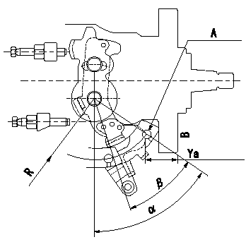
1. Measure dimension Ya between the end of the lever and the flange face.
2. Measure the lever angle from the pin hole R (plate).
A = lever angle measuring position
B = flange face
----------
Ya=23.7~28.3mm R=49mm
----------
Ya=23.7~28.3mm R=49mm
----------
Ya=23.7~28.3mm R=49mm
----------
Ya=23.7~28.3mm R=49mm
0000001901 ACCELERATOR SWITCH ADJ

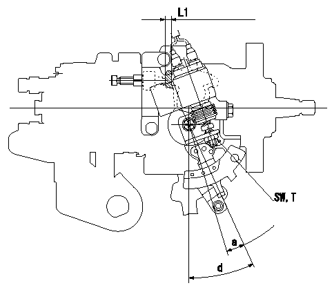
Accelerator switch adjustment
ON - OFF changeover point: from idle to a (shim thickness A = L)
Idle~c: ON
c~full: OFF
A = shim thickness
----------
a=8+-2deg b=8deg c=8deg L1=5.2+-0.13mm
----------
a=8+-2deg d=25+-4deg SW=SW10 T=6~9N-m(0.6~0.9kgf-m) L1=5.2mm
----------
a=8+-2deg b=8deg c=8deg L1=5.2+-0.13mm
----------
a=8+-2deg d=25+-4deg SW=SW10 T=6~9N-m(0.6~0.9kgf-m) L1=5.2mm
Information:
To avoid possible engine damage or another immediate shutdown, the water temperature fault must be corrected before attempting to restart the engine.
Even though the starter motor circuit can now be engaged, there is no fuel flow to the engine. The fuel flow to the engine is stopped until the coolant temperature falls below the rating for the water temperature contactor switch (WTS). When the coolant temperature falls below the rating for the water temperature contactor switch (WTS), the contactor switch opens again. The fuel shutoff solenoid is de-energized when the switch reopens. This allows fuel flow to the engine. The engine can then be restarted.2301A Electric Governor Control
The 2301A Electric Governor Control activates all of the components that are in the electric protection system. The components are activated in the same manner when the nonelectric governor is used. One difference exists in the main circuit. The fuel shutoff solenoid (FSOS) (line 43) is not used.When the electric governor control is used, the engine must run in a normal condition in order for the electric circuit to operate in the manner that is described below.
Current flows from the terminals (TS-28) (line 43) and (TS-31) (line 44), which are located on the terminal strip in the junction box.
Current from terminals (TS-28) (line 43) and (TS-31) (line 44) flows through the preregulator (PR) (line 48) or the fuse (F4) to the electric governor control.
When the engine flywheel is rotating, the current also flows through the electric governor actuator (EGA) (line 52). When a fault in the system causes the current to energize the slave relay (SR1), the following events occur in the electric circuit in order to stop the engine.
The slave relay (SR1) opens across the contacts (SR1-30) and (SR1-87a) (line 45). The relay closes across the contacts (SR1-30) and (SR1-87) (line 43).
When the circuit opens across contacts (SR1-30) and (SR1-87a), the current is stopped to the electric governor control.
Current to the electric governor actuator (EGA) is also stopped.
The mechanical spring load in the electric governor actuator (EGA) will now move the fuel control rod in order to stop fuel flow to the engine.Note: With the exception of the differences that are described in this section of the manual, all of the fault circuits in the electric protection system are identical for the 2301A Electric Governor Control and for the nonelectric governor control.
Illustration 5 g00292456
Junction Box Wiring for ETS with OP, WT, and OS that does not require a switchgear for use on 3200 through 3400 Engines
Illustration 6 g00292457
JIC Schematic for ETS with OP, WT, and OS that does not require a switchgear for use on 3200 through 3400 Engines
Illustration 7 g00292458
IEC Schematic for ETS with OP, WT, and OS that does not require a switchgear for use on 3200 through 3400 Engines
Illustration 8 g00292474
6I-1862 Wiring Harness for ETS with OP, WT, and OS that does not require a switchgear for use on 3200 through 3400 Engines
Illustration 9 g00292459
Junction Box Wiring for ETS with OP, WT, and OS that does not require a switchgear for