Information injection-pump assembly
BOSCH
9 460 612 736
9460612736
ZEXEL
104740-8790
1047408790
MITSUBISHI
MD306843
md306843

Rating:
Components :
| 0. | INJECTION-PUMP ASSEMBLY | 104740-8790 |
| 1. | _ | |
| 2. | FUEL INJECTION PUMP | 104640-8790 |
| 3. | NUMBER PLATE | 146954-4600 |
| 4. | _ | 479771-0520 |
| 5. | CAPSULE | |
| 6. | ADJUSTING DEVICE | |
| 7. | NOZZLE AND HOLDER ASSY | 105148-1112 |
| 8. | Nozzle and Holder | MD103301 |
| 9. | Open Pre:MPa(Kqf/cm2) | 11.8{120} |
| 10. | NOZZLE-HOLDER | 105078-0012 |
| 11. | NOZZLE | 105007-1120 |
Scheme ###:
| 1/6. | [1] | 146601-0700 | PACKING RING |
| 6. | [1] | 146100-0120 | SUPPLY PUMP |
| 9. | [1] | 146103-0000 | COVER |
| 10. | [2] | 139104-0000 | FLAT-HEAD SCREW |
| 12. | [1] | 146200-0320 | DRIVE SHAFT |
| 12/1. | [1] | 146200-0300 | DRIVE SHAFT |
| 12/2. | [1] | 146201-0000 | WOODRUFF KEY |
| 12/3. | [2] | 146202-0100 | DAMPER |
| 12/4. | [1] | 146203-0000 | TOOTHED GEAR |
| 17. | [1] | 146204-0000 | PLAIN WASHER |
| 20. | [1] | 146210-4120 | ROLLER SET |
| 24. | [1] | 146303-0100 | BEARING PIN |
| 25. | [1] | 146304-0000 | BEARING PIN |
| 26. | [1] | 146305-0000 | CLAMPING BAND |
| 27. | [1] | 146205-0000 | SLOTTED WASHER |
| 29. | [1] | 146220-2120 | CAM PLATE |
| 30. | [1] | 146600-0800 | O-RING |
| 31. | [1] | 146300-2400 | PUMP PLUNGER |
| 32. | [1] | 146301-0000 | SLIDING PIECE |
| 33. | [1] | 146603-0700 | SHIM |
| 34. | [1] | 146302-3600 | COMPRESSION SPRING |
| 34B. | [1] | 146302-3500 | COMPRESSION SPRING |
| 34C. | [1] | 146302-3700 | COMPRESSION SPRING |
| 35/1. | [0] | 146603-0700 | SHIM D17.5&7.5T0.60 |
| 35/1. | [0] | 146603-0800 | SHIM D17.5&7.5T0.70 |
| 35/1. | [0] | 146603-0900 | SHIM D17.5&7.5T0.90 |
| 35/1. | [0] | 146603-1000 | SHIM D17.5&7.5T1.00 |
| 35/1. | [0] | 146603-1100 | SHIM D17.5&7.5T1.20 |
| 35/1. | [0] | 146603-3600 | SHIM D17.5&7.5T2.40 |
| 36. | [1] | 146600-0800 | O-RING |
| 37. | [1] | 146310-0700 | COVER |
| 38. | [2] | 146620-5000 | BLEEDER SCREW |
| 39. | [1] | 146310-0100 | COVER |
| 40. | [2] | 146620-5000 | BLEEDER SCREW |
| 43. | [1] | 146230-0000 | SHIM |
| 44. | [1] | 146230-0100 | PLAIN WASHER |
| 45. | [1] | 146231-0001 | SLOTTED WASHER |
| 47. | [2] | 146233-0000 | SLOTTED WASHER |
| 48/1. | [1] | 146603-0100 | SHIM D17.0&5.2T0.80 |
| 48/1. | [1] | 146603-0200 | SHIM D17.0&5.2T1.00 |
| 48/1. | [1] | 146603-0300 | SHIM D17.0&5.2T1.20 |
| 48/1. | [1] | 146603-0400 | SHIM D17.0&5.2T1.50 |
| 48/1. | [1] | 146690-1400 | SHIM D17&5.2T0.9 |
| 48/1. | [1] | 146690-1500 | SHIM D17&5.2T1.1 |
| 48/1. | [1] | 146690-1600 | SHIM D17&5.2T1.3 |
| 48/1. | [1] | 146690-1700 | SHIM D17&5.2T1.4 |
| 48/1. | [1] | 146690-1800 | SHIM D17&5.2T1.6 |
| 49. | [2] | 146234-0500 | GUIDE PIN |
| 50. | [1] | 146401-0221 | HYDRAULIC HEAD |
| 50. | [1] | 146401-0221 | HYDRAULIC HEAD |
| 50. | [1] | 146401-0221 | HYDRAULIC HEAD |
| 51. | [1] | 146600-0000 | O-RING |
| 52/1. | [1] | 146420-0200 | SHIM D9.5&3.0T1.94 |
| 52/1. | [1] | 146420-0700 | SHIM D9.5&3.0T2.04 |
| 52/1. | [1] | 146420-1200 | SHIM D9.5&3.0T2.14 |
| 52/1. | [1] | 146420-1700 | SHIM D9.5&3.0T2.24 |
| 52/1. | [1] | 146420-2200 | SHIM D9.5&3.0T2.34 |
| 52/1. | [1] | 146420-2700 | SHIM D9.5&3.0T2.44 |
| 52/1. | [1] | 146420-3200 | SHIM D9.5&3.0T2.54 |
| 52/1. | [1] | 146420-3700 | SHIM D9.5&3.0T2.64 |
| 52/1. | [1] | 146420-5600 | SHIM D9.5&3.0T1.84 |
| 54. | [4] | 146433-0100 | GASKET |
| 55. | [4] | 146430-0320 | DELIVERY-VALVE ASSEMBLY VE4 |
| 56. | [4] | 146432-0000 | COMPRESSION SPRING |
| 58. | [4] | 146440-0320 | FITTING |
| 60. | [3] | 139106-0100 | FLAT-HEAD SCREW |
| 67. | [1] | 146820-2320 | GOVERNOR COVER |
| 67/1. | [1] | 146508-8221 | GOVERNOR COVER |
| 67/2. | [1] | 146515-0320 | CONTROL SHAFT |
| 67/3. | [1] | 146600-0100 | O-RING |
| 67/4. | [1] | 139310-0200 | PLAIN WASHER |
| 67/13. | [1] | 146621-1700 | UNION NUT |
| 67/14. | [1] | 146621-1700 | UNION NUT |
| 67/15. | [1] | 146526-3400 | BLEEDER SCREW |
| 67/16. | [1] | 146526-2800 | BLEEDER SCREW |
| 67/78. | [1] | 146600-4400 | SEAL RING |
| 67/200. | [1] | 139308-0300 | PLAIN WASHER |
| 67/201. | [1] | 146545-3400 | THREADED PIN L53.00 |
| 67/201B. | [1] | 146545-3500 | THREADED PIN L55.00 |
| 67/201C. | [1] | 146545-3600 | THREADED PIN L57.00 |
| 67/202. | [1] | 139208-0900 | UNION NUT |
| 67/203. | [1] | 146600-1200 | O-RING |
| 72. | [1] | 146830-8020 | CONTROL LEVER STAMP 30-80 |
| 72B. | [1] | 146830-8120 | CONTROL LEVER STAMP 30-81 |
| 73. | [1] | 014110-6440 | LOCKING WASHER D12.2&6.1T1.5 |
| 75. | [1] | 013020-6040 | UNION NUT |
| 95. | [1] | 146551-6120 | FULCRUM LEVER |
| 104. | [2] | 146568-0000 | SLOTTED SPRING PIN |
| 105. | [2] | 026508-1140 | GASKET D11.4&8.2T1.0 |
| 106. | [2] | 146588-0500 | COILED SPRING |
| 107. | [1] | 146569-0300 | UNION NUT |
| 108. | [1] | 146570-0420 | GOVERNOR SHAFT |
| 109. | [1] | 146600-0400 | O-RING |
| 110/1. | [1] | 146571-0000 | SHIM D20.2&8.3T1.05 |
| 110/1. | [1] | 146571-0100 | SHIM D20.2&8.3T1.25 |
| 110/1. | [1] | 146571-0200 | SHIM D20.2&8.3T1.45 |
| 110/1. | [1] | 146571-0300 | SHIM D20.2&8.3T1.65 |
| 110/1. | [1] | 146571-0400 | SHIM D20.2&8.3T1.85 |
| 111. | [1] | 146602-0600 | PLAIN WASHER |
| 112. | [1] | 146572-0020 | FLYWEIGHT ASSEMBLY |
| 114. | [1] | 146602-0500 | PLAIN WASHER |
| 115. | [1] | 146975-8000 | SLIDING SLEEVE |
| 116. | [1] | 146576-0000 | SEALING CAP |
| 117/1. | [1] | 146577-2200 | PLUG L2.90 |
| 117/1. | [1] | 146577-2300 | PLUG L3.10 |
| 117/1. | [1] | 146577-2400 | PLUG L3.30 |
| 117/1. | [1] | 146577-2500 | PLUG L3.50 |
| 117/1. | [1] | 146577-2600 | PLUG L3.70 |
| 117/1. | [1] | 146577-2700 | PLUG L3.90 |
| 117/1. | [1] | 146577-2800 | PLUG L4.10 |
| 117/1. | [1] | 146577-2900 | PLUG L4.30 |
| 117/1. | [1] | 146577-3000 | PLUG L4.50 |
| 117/1. | [1] | 146577-7100 | PLUG L3.0 |
| 117/1. | [1] | 146577-7200 | PLUG L3.2 |
| 117/1. | [1] | 146577-7300 | PLUG L3.4 |
| 117/1. | [1] | 146577-7400 | PLUG L3.6 |
| 117/1. | [1] | 146577-7500 | PLUG L3.8 |
| 117/1. | [1] | 146577-7600 | PLUG L4.0 |
| 117/1. | [1] | 146577-7700 | PLUG L4.2 |
| 117/1. | [1] | 146577-7800 | PLUG L4.4 |
| 120. | [1] | 146579-5320 | RETAINING PIN |
| 122. | [1] | 146580-2300 | GOVERNOR SPRING |
| 123. | [4] | 139106-0200 | FLAT-HEAD SCREW |
| 130. | [1] | 146421-0020 | CAPSULE |
| 130/2. | [1] | 026508-1140 | GASKET D11.4&8.2T1.0 |
| 130/3. | [1] | 146422-0000 | BLEEDER SCREW |
| 130/4. | [1] | 146600-0500 | O-RING |
| 133. | [1] | 146600-0600 | O-RING |
| 134. | [1] | 146600-0700 | O-RING |
| 135. | [1] | 146110-0220 | CONTROL VALVE STAMP 02 |
| 135/5. | [1] | 146114-0000 | SPRING WASHER |
| 136. | [1] | 146120-0020 | OVER FLOW VALVE |
| 137. | [2] | 139512-0500 | GASKET |
| 138. | [1] | 146605-8620 | INLET UNION |
| 200. | [1] | 146206-0100 | COILED SPRING |
| 205. | [1] | 029470-4030 | WOODRUFF KEY |
| 217. | [1] | 146542-5300 | SLOTTED WASHER |
| 218. | [1] | 146592-2500 | COILED SPRING |
| 219. | [1] | 146541-3000 | BUSHING |
| 220. | [1] | 146592-2600 | COILED SPRING |
| 224. | [1] | 139006-4700 | BLEEDER SCREW |
| 225. | [1] | 146931-2420 | BRACKET |
| 226. | [1] | 010206-1240 | HEX-SOCKET-HEAD CAP SCREW |
| 229. | [1] | 146929-0220 | BRACKET |
| 230. | [1] | 146629-2120 | BRACKET |
| 231. | [1] | 139006-4600 | BLEEDER SCREW |
| 232. | [1] | 146931-3200 | BRACKET STAMP 132 |
| 233. | [1] | 146658-9020 | WIRE |
| 234. | [1] | 139006-4800 | BLEEDER SCREW |
| 235. | [1] | 146659-0600 | CLAMPING BAND |
| 237. | [1] | 146620-0200 | HEX-SOCKET-HEAD CAP SCREW |
| 240. | [1] | 146650-1220 | PULLING ELECTROMAGNET |
| 240/8. | [1] | 146600-1700 | O-RING |
| 243. | [1] | 146621-1000 | UNION NUT |
| 245. | [2] | 139512-0500 | GASKET |
| 246. | [1] | 146125-0300 | EYE BOLT |
| 247. | [1] | 146666-0120 | INLET UNION |
| 253. | [1] | 139006-4600 | BLEEDER SCREW |
| 275. | [1] | 146612-4800 | BRACKET |
| 276. | [2] | 010010-1640 | BLEEDER SCREW |
| 280. | [1] | 146361-7020 | START ADVANCE ASSY STAMP 119 |
| 281. | [1] | 146600-0800 | O-RING |
| 282. | [2] | 010206-1240 | HEX-SOCKET-HEAD CAP SCREW |
| 286. | [1] | 020106-3040 | BLEEDER SCREW |
| 287. | [1] | 014010-6140 | PLAIN WASHER D13&6.5T1.0 |
| 800S. | [1] | 146018-5120 | PUMP HOUSING |
| 800S/1/6. | [1] | 146601-0700 | PACKING RING |
| 804S. | [1] | 146232-0320 | COMPRESSION SPRING |
| 805S. | [1] | 146574-0120 | PARTS SET |
| 810S. | [1] | 146600-1120 | REPAIR SET |
| 821S. | [1] | 146210-5720 | ROLLER SET |
| 835S. | [1] | 146598-1000 | CAP |
| 836S/1. | [1] | 146598-0600 | CAP L18 |
| 836S/1. | [1] | 146598-0700 | CAP L21 |
| 836S/1. | [1] | 146598-0800 | CAP L24 |
| 836S/1. | [1] | 146598-0900 | CAP L27 |
| 903. | [1] | 479771-0520 | PULSE GENERATOR |
| 906. | [1] | 146954-4600 | NAMEPLATE |
| 910S. | [1] | 146600-4020 | PARTS SET |
| 910S. | [1] | 146600-4020 | PARTS SET |
| 911S. | [1] | 479771-0520 | PULSE GENERATOR |
| 912S. | [1] | 026508-1140 | GASKET D11.4&8.2T1.0 |
| 913S. | [1] | 146422-0000 | BLEEDER SCREW |
| 914S. | [1] | 146699-0020 | VALVE SET |
| 914S. | [1] | 146699-0020 | VALVE SET |
| 914S. | [1] | 146699-0020 | VALVE SET |
| 915S. | [1] | 146658-9020 | WIRE |
| 916S. | [1] | 025804-1610 | WOODRUFF KEY |
Include in #2:
104740-8790
as INJECTION-PUMP ASSEMBLY
Cross reference number
BOSCH
9 460 612 736
9460612736
ZEXEL
104740-8790
1047408790
MITSUBISHI
MD306843
md306843
Zexel num
Bosch num
Firm num
Name
104740-8790
9 460 612 736
MD306843 MITSUBISHI
INJECTION-PUMP ASSEMBLY
4D56 K 11CJ INJECTION PUMP ASSY VE4 VE
4D56 K 11CJ INJECTION PUMP ASSY VE4 VE
Calibration Data:
Adjustment conditions
Test oil
1404 Test oil ISO4113orSAEJ967d
1404 Test oil ISO4113orSAEJ967d
Test oil temperature
degC
45
45
50
Nozzle
105000-2010
Bosch type code
NP-DN12SD12TT
Nozzle holder
105780-2080
Opening pressure
MPa
14.7
14.7
15.19
Opening pressure
kgf/cm2
150
150
155
Injection pipe
Inside diameter - outside diameter - length (mm) mm 2-6-840
Inside diameter - outside diameter - length (mm) mm 2-6-840
Transfer pump pressure
kPa
20
20
20
Transfer pump pressure
kgf/cm2
0.2
0.2
0.2
Direction of rotation (viewed from drive side)
Right R
Right R
Injection timing adjustment
Pump speed
r/min
1250
1250
1250
Average injection quantity
mm3/st.
45.8
45.3
46.3
Difference in delivery
mm3/st.
3
Basic
*
Injection timing adjustment_02
Pump speed
r/min
2550
2550
2550
Average injection quantity
mm3/st.
18.1
14.6
21.6
Injection timing adjustment_03
Pump speed
r/min
2100
2100
2100
Average injection quantity
mm3/st.
39.2
37.1
41.3
Injection timing adjustment_04
Pump speed
r/min
1750
1750
1750
Average injection quantity
mm3/st.
40.2
38.2
42.2
Injection timing adjustment_05
Pump speed
r/min
1250
1250
1250
Average injection quantity
mm3/st.
45.8
44.8
46.8
Injection timing adjustment_06
Pump speed
r/min
600
600
600
Average injection quantity
mm3/st.
44.3
42.3
46.3
Injection quantity adjustment
Pump speed
r/min
2550
2550
2550
Average injection quantity
mm3/st.
18.1
15.1
21.1
Difference in delivery
mm3/st.
4
Basic
*
Injection quantity adjustment_02
Pump speed
r/min
2900
2900
2900
Average injection quantity
mm3/st.
5
Governor adjustment
Pump speed
r/min
375
375
375
Average injection quantity
mm3/st.
12
10.5
13.5
Difference in delivery
mm3/st.
2
Basic
*
Governor adjustment_02
Pump speed
r/min
750
750
750
Average injection quantity
mm3/st.
3
Governor adjustment_03
Pump speed
r/min
600
600
600
Average injection quantity
mm3/st.
7
Governor adjustment_04
Pump speed
r/min
375
375
375
Average injection quantity
mm3/st.
12
10
14
Timer adjustment
Pump speed
r/min
100
100
100
Average injection quantity
mm3/st.
73
63
83
Basic
*
Remarks
IDLE
IDLE
Speed control lever angle
Pump speed
r/min
375
375
375
Average injection quantity
mm3/st.
0
0
0
Remarks
Magnet OFF at idling position
Magnet OFF at idling position
0000000901
Pump speed
r/min
1250
1250
1250
Overflow quantity
cm3/min
420
288
552
Stop lever angle
Pump speed
r/min
1250
1250
1250
Pressure
kPa
470.5
441
500
Pressure
kgf/cm2
4.8
4.5
5.1
Basic
*
Stop lever angle_02
Pump speed
r/min
1250
1250
1250
Pressure
kPa
470.5
441
500
Pressure
kgf/cm2
4.8
4.5
5.1
Stop lever angle_03
Pump speed
r/min
2100
2100
2100
Pressure
kPa
666.5
637
696
Pressure
kgf/cm2
6.8
6.5
7.1
0000001101
Pump speed
r/min
1250
1250
1250
Timer stroke
mm
3.7
3.5
3.9
Basic
*
_02
Pump speed
r/min
500
500
500
Timer stroke
mm
1.2
0.6
1.8
_03
Pump speed
r/min
750
750
750
Timer stroke
mm
2
1.4
2.6
_04
Pump speed
r/min
1250
1250
1250
Timer stroke
mm
3.7
3.4
4
_05
Pump speed
r/min
1750
1750
1750
Timer stroke
mm
5.8
5.2
6.4
_06
Pump speed
r/min
2100
2100
2100
Timer stroke
mm
7.2
6.6
7.8
0000001201
Max. applied voltage
V
8
8
8
Test voltage
V
13
12
14
0000001401
Pump speed
r/min
1250
1250
1250
Average injection quantity
mm3/st.
35.7
35.2
36.2
Timer stroke variation dT
mm
0.6
0.4
0.8
Basic
*
_02
Pump speed
r/min
1250
1250
1250
Average injection quantity
mm3/st.
35.7
34.7
36.7
Timer stroke variation dT
mm
0.6
0.3
0.9
_03
Pump speed
r/min
1250
1250
1250
Average injection quantity
mm3/st.
28.2
26.7
29.7
Timer stroke variation dT
mm
1.4
0.9
1.9
Timing setting
K dimension
mm
3.3
3.2
3.4
KF dimension
mm
5.8
5.7
5.9
MS dimension
mm
1.2
1.1
1.3
Control lever angle alpha
deg.
55
51
59
Control lever angle beta
deg.
41
36
46
Test data Ex:
0000001801 W-CSD ADJUSTMENT

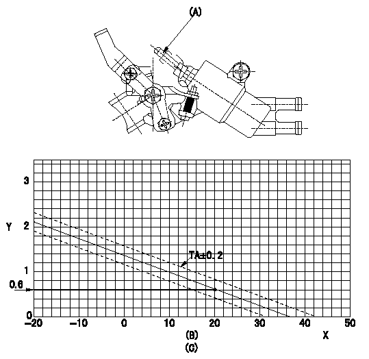
Adjustment of the W-CSD
1. Adjustment of the advance angle of the timer
(1)Determine the timer advance angle using the following graph.
(2)(1) Adjust with the screw (A) so that the timer advance angle determined in the item (1) is obtained.
X:Temperature t (deg C)
Y:Timer stroke TA (mm)
(B): Timer stroke TA (mm):
----------
----------
(C)=TA=-0.0376t+1.38(-20<=t)
----------
----------
(C)=TA=-0.0376t+1.38(-20<=t)
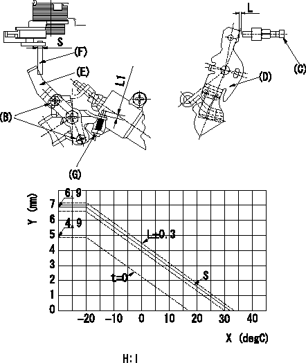
0000001901 W-FICD LEVER ADJUSTMENT

2. Adjustment of the W-FICD
(1)Insert a block gauge L2 determined from the graph below between the control lever (D) and the idling stopper bolt (C).
(2)Insert a shim S between the W-FICD lever (E) and the control lever (F). Adjust the W-FICD lever (E) so that it contacts the control lever (F) and fix it using bolt (B).
TT
Note:
a) The temperature of wax at the time of adjustment must not exceed a.
b) After completion of the adjustment, confirm that allowance for adjustment of the screw (G) is at least L1.
X:Temperature X (deg C)
Y:Control lever: dimension L (mm) (control lever position)
H:Graph, L - X graph
----------
L2=L+-0.05mm S=3+-0.05mm T=3.4~4.9N-m(0.35~0.5kgf-m) a=30degC L1=3mm
----------
L1=3++mm S=(3mm) H:L=-0.132X+4.29(-20<=X)(S=3+-0.05)
----------
L2=L+-0.05mm S=3+-0.05mm T=3.4~4.9N-m(0.35~0.5kgf-m) a=30degC L1=3mm
----------
L1=3++mm S=(3mm) H:L=-0.132X+4.29(-20<=X)(S=3+-0.05)
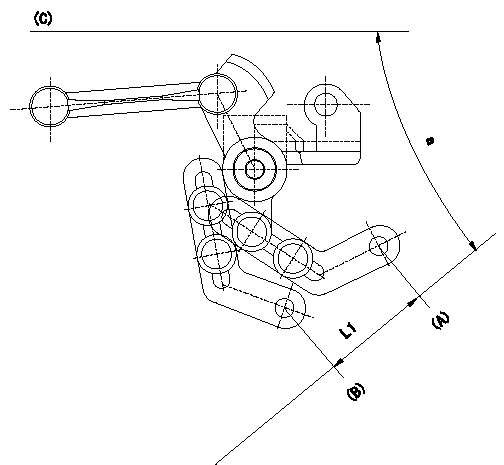
0000002001 ACCELERATOR LINK STROKE

Accelerator link stroke adjustment
As shown in the figure, adjust so that the accelerator link's stroke between idle (A) and full speed (B) is L1.
(C) = Injection pump
----------
L1=32.9+-1mm
----------
L1=32.9+-1mm a=40deg
----------
L1=32.9+-1mm
----------
L1=32.9+-1mm a=40deg
Information:
If the vehicle has a disconnect switch, the starting circuit can operate only after the disconnect switch is put in the ON position.The starting circuit is in operation only when the start switch is activated.The low amperage circuit and the charging circuit are both connected to the same side of the ammeter. The starting circuit connects to the opposite side of the ammeter.
Never operate the alternator without the battery in the circuit. Making or breaking an alternator connection with heavy load on the circuit can cause damage to the regulator.
Charging System Components
Alternator
Alternator Components (Typical Example)
(1) Brush holder. (2) Rear frame. (3) Rotor. (4) Stator. (5) Drive end frame. (6) Fan assembly. (7) Slip rings. (8) Rectifier.The alternator has three phase, full-wave, rectified output. It is a brush type alternator.The alternator is an electrical and mechanical component driven by a belt from engine rotation. It is used to charge the storage battery during engine operation. The alternator is cooled by a fan that is a part of the alternator. The fan pulls air through holes in the back of the alternator. The air exits the front of the alternator, cooling it in the process.The alternator converts mechanical and magnetic energy to alternating current (AC) and voltage. This process is done by rotating a direct current (DC) electromagnetic field (rotor) inside a three phase stator. The alternating current and voltage (generated by the stator) are changed to direct current by a three phase, full wave rectifier system using six silicone rectifier diodes. The alternator also has a diode trio which is an assembly made up of three exciter diodes. The diode trio rectifies field current needed to start the charging process. Direct current flows to the alternator output terminal.A solid state regulator is installed in the back of the alternator. Two brushes conduct current, through two slip rings, to the field coil on the rotor.There is also a capacitor mounted in the back of the alternator. The capacitor protects the rectifier from high voltages. It also suppresses radio noise.Regulator
The voltage regulator is a solid state (transistor, stationary parts) electronic switch which controls the alternator output. The regulator limits the alternator voltage to a preset value by controlling the field current. It feels the voltage in the system and switches "ON" and "OFF" many times a second to control the field current (DC current to the field windings) for the alternator to make the needed voltage output. Refer to Service Manual, SENR3862, for detailed service information for the Delco Remy 27 SI Series Alternator. For engines which have the alternator connected to an engine component, the ground strap must connect that component to the frame or to the battery ground.Starting System Components
Starter Solenoid
A solenoid is a magnetic switch that does two basic operations:1. Closes the high current starter motor circuit with a low current start switch circuit.2. Engages the starter motor pinion with the ring gear.
Typical SolenoidThe solenoid switch is made of an electromagnet (one or two sets of windings) around
Have questions with 104740-8790?
Group cross 104740-8790 ZEXEL
Mitsubishi
Mitsubishi
Mitsubishi
Mitsubishi
Mitsubishi
Mitsubishi
104740-8790
9 460 612 736
MD306843
INJECTION-PUMP ASSEMBLY
4D56
4D56
