Information injection-pump assembly
ZEXEL
104740-8660
1047408660
MITSUBISHI
ME200202
me200202

Rating:
Cross reference number
ZEXEL
104740-8660
1047408660
MITSUBISHI
ME200202
me200202
Zexel num
Bosch num
Firm num
Name
Calibration Data:
Adjustment conditions
Test oil
1404 Test oil ISO4113orSAEJ967d
1404 Test oil ISO4113orSAEJ967d
Test oil temperature
degC
45
45
50
Nozzle
105780-0060
Bosch type code
NP-DN0SD1510
Nozzle holder
105780-2150
Opening pressure
MPa
13
13
13.3
Opening pressure
kgf/cm2
133
133
136
Injection pipe
157805-7320
Injection pipe
Inside diameter - outside diameter - length (mm) mm 2-6-450
Inside diameter - outside diameter - length (mm) mm 2-6-450
Joint assembly
157641-4720
Tube assembly
157641-4020
Transfer pump pressure
kPa
20
20
20
Transfer pump pressure
kgf/cm2
0.2
0.2
0.2
Direction of rotation (viewed from drive side)
Right R
Right R
(Solenoid timer adjustment condition)
With S/T O-ring; S/T OFF. OFF
With S/T O-ring; S/T OFF. OFF
Injection timing adjustment
Pump speed
r/min
1000
1000
1000
Average injection quantity
mm3/st.
62.7
62.2
63.2
Difference in delivery
mm3/st.
5
Basic
*
Oil temperature
degC
50
48
52
Injection timing adjustment_02
Pump speed
r/min
600
600
600
Average injection quantity
mm3/st.
60.2
57.7
62.7
Oil temperature
degC
50
48
52
Injection timing adjustment_03
Pump speed
r/min
1000
1000
1000
Average injection quantity
mm3/st.
62.7
61.7
63.7
Difference in delivery
mm3/st.
5.5
Basic
*
Oil temperature
degC
50
48
52
Remarks
Full
Full
Injection timing adjustment_04
Pump speed
r/min
1500
1500
1500
Average injection quantity
mm3/st.
61.6
61.6
64.1
Oil temperature
degC
50
48
52
Injection timing adjustment_05
Pump speed
r/min
2000
2000
2000
Average injection quantity
mm3/st.
60.1
57.1
63.1
Oil temperature
degC
50
48
52
Injection quantity adjustment
Pump speed
r/min
2475
2475
2475
Average injection quantity
mm3/st.
30.5
27.5
33.5
Difference in delivery
mm3/st.
9
Basic
*
Oil temperature
degC
52
50
54
Injection quantity adjustment_02
Pump speed
r/min
2475
2475
2475
Average injection quantity
mm3/st.
30.5
25.5
35.5
Difference in delivery
mm3/st.
9.5
Basic
*
Oil temperature
degC
52
50
54
Injection quantity adjustment_03
Pump speed
r/min
2800
2800
2800
Average injection quantity
mm3/st.
5
Oil temperature
degC
55
52
58
Governor adjustment
Pump speed
r/min
350
350
350
Average injection quantity
mm3/st.
8.3
6.3
10.3
Difference in delivery
mm3/st.
2
Basic
*
Oil temperature
degC
48
46
50
Governor adjustment_02
Pump speed
r/min
350
350
350
Average injection quantity
mm3/st.
8.3
5.8
10.8
Difference in delivery
mm3/st.
2.5
Basic
*
Oil temperature
degC
48
46
50
Timer adjustment
Pump speed
r/min
150
150
150
Average injection quantity
mm3/st.
48
38
58
Basic
*
Oil temperature
degC
48
46
50
Remarks
IDLE
IDLE
Timer adjustment_02
Pump speed
r/min
150
150
150
Average injection quantity
mm3/st.
48
38
58
Basic
*
Oil temperature
degC
48
46
50
Speed control lever angle
Pump speed
r/min
350
350
350
Average injection quantity
mm3/st.
0
0
0
Oil temperature
degC
48
46
50
Remarks
Magnet OFF at idling position
Magnet OFF at idling position
0000000901
Pump speed
r/min
1100
1100
1100
Overflow quantity with S/T ON
cm3/min
830
700
960
Overflow quantity with S/T OFF
cm3/min
910
780
1040
Oil temperature
degC
50
48
52
Stop lever angle
Pump speed
r/min
1250
1250
1250
Pressure with S/T ON
kPa
559
530
588
Pressure with S/T ON
kgf/cm2
5.7
5.4
6
Pressure with S/T OFF
kPa
471
451
491
Pressure with S/T OFF
kgf/cm2
4.8
4.6
5
Basic
*
Oil temperature
degC
50
48
52
Stop lever angle_02
Pump speed
r/min
700
700
700
Pressure with S/T ON
kPa
431
382
480
Pressure with S/T ON
kgf/cm2
4.4
3.9
4.9
Pressure with S/T OFF
kPa
314
265
363
Pressure with S/T OFF
kgf/cm2
3.2
2.7
3.7
Oil temperature
degC
50
48
52
Stop lever angle_03
Pump speed
r/min
1000
1000
1000
Pressure with S/T ON
kPa
500
451
549
Pressure with S/T ON
kgf/cm2
5.1
4.6
5.6
Pressure with S/T OFF
kPa
412
373
451
Pressure with S/T OFF
kgf/cm2
4.2
3.8
4.6
Oil temperature
degC
50
48
52
Stop lever angle_04
Pump speed
r/min
1250
1250
1250
Pressure with S/T ON
kPa
559
520
598
Pressure with S/T ON
kgf/cm2
5.7
5.3
6.1
Pressure with S/T OFF
kPa
471
442
500
Pressure with S/T OFF
kgf/cm2
4.8
4.5
5.1
Basic
*
Oil temperature
degC
50
48
52
Stop lever angle_05
Pump speed
r/min
1500
1500
1500
Pressure with S/T ON
kPa
618
569
667
Pressure with S/T ON
kgf/cm2
6.3
5.8
6.8
Pressure with S/T OFF
kPa
530
481
579
Pressure with S/T OFF
kgf/cm2
5.4
4.9
5.9
Oil temperature
degC
50
48
52
Stop lever angle_06
Pump speed
r/min
2000
2000
2000
Pressure with S/T OFF
kPa
628
579
677
Pressure with S/T OFF
kgf/cm2
6.4
5.9
6.9
Oil temperature
degC
50
48
52
0000001101
Pump speed
r/min
1250
1250
1250
Timer stroke with S/T ON
mm
4.4
4
4.8
Timer stroke with S/T OFF
mm
2.9
2.7
3.1
Basic
*
Oil temperature
degC
50
48
52
_02
Pump speed
r/min
700
700
700
Timer stroke with S/T ON
mm
2
1.3
2.7
Timer stroke with S/T OFF
mm
0.8
Oil temperature
degC
50
48
52
_03
Pump speed
r/min
1250
1250
1250
Timer stroke with S/T ON
mm
4.4
3.8
5
Timer stroke with S/T OFF
mm
2.9
2.5
3.3
Basic
*
Oil temperature
degC
50
48
52
_04
Pump speed
r/min
2400
2400
2400
Timer stroke with S/T OFF
mm
7.4
6.9
7.8
Oil temperature
degC
52
50
54
0000001201
Max. applied voltage
V
8
8
8
Test voltage
V
13
12
14
Timing setting
K dimension
mm
3.3
3.2
3.4
KF dimension
mm
5.8
5.7
5.9
MS dimension
mm
0.9
0.8
1
Control lever angle alpha
deg.
59
55
63
Control lever angle beta
deg.
42
37
47
Test data Ex:
0000001801 POTENTIOMETER ADJUSTMENT
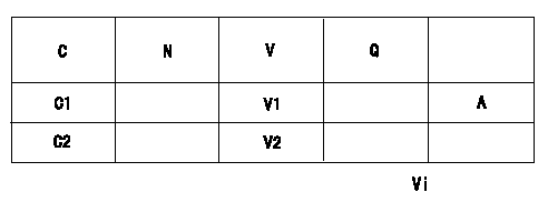
Adjustment of the potentiometer
Vi:Applied voltage
C:Position of the control lever
N:Pump speed
V:Output voltage
Q:Injection quantity
A:Adjusting point
C1:Idling
C2:Full speed
----------
----------
V1=1.6+-0.03(V) V2=(8.6(V)) Vi=10(V)
----------
----------
V1=1.6+-0.03(V) V2=(8.6(V)) Vi=10(V)
0000001901 W-FICD LEVER ADJUSTMENT
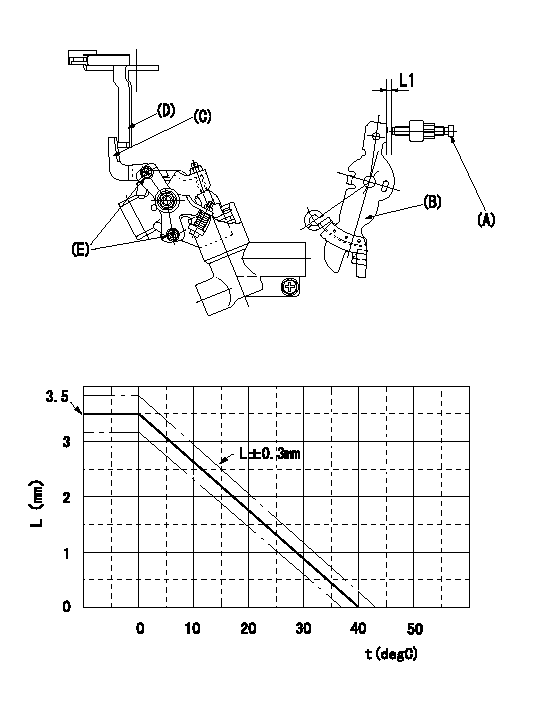
2. W-FICD (E) adjustment
(1)Insert a block gauge L1 determined from the graph between the control lever (B) and the idling set screw (A).
Graph for calculating L (mm) L = -0.088t+3.5
(2)Fix bolt (E) in the position where W-FICD lever (C) contacts the control lever (D). (Tighten to torque T.)
(3)The temperature of the wax at adjustment must not exceed a.
t:Temperature
L:Control lever L dimension (control lever position)
----------
L1=L+-0.3(mm) T=3.4~4.9(Nm)(0.35~0.5(kgfm)) a=35(degC)
----------
L1=L+-0.3(mm)
----------
L1=L+-0.3(mm) T=3.4~4.9(Nm)(0.35~0.5(kgfm)) a=35(degC)
----------
L1=L+-0.3(mm)
Information:
Recommended Procedure With Chassis Dynamometer
Possible Causes/Corrections Minor Operating FaultsTo help identify a problem before a more involved troubleshooting procedure is started, follow the procedure given in the "Primary Engine Checks" section. Fuel Ratio Control Out Of Adjustment Or DefectiveFollow the procedure in the Testing and Adjusting Section of this Service Manual. Check Engine PerformanceDo a Power Analysis Report (PAR), Level II, to check engine performance. Refer to LEBV2810 and SEHS7886 for the tooling and procedures to use. Be sure to make a record of the temperatures for inlet air, fuel (at filter base), lubricating oil and coolant. Make the necessary adjustments or repairs to the engine if needed.At this point, the governor fuel settings should be verified. See the Testing and Adjusting Section of this Service Manual for the necessary procedures. Also, refer back to the information learned earlier (see "Owner/Operator Input" section) about the truck specifications and application and judge whether or not the engine is performing as expected or customer expectation is realistic.Recommended Procedure Without Chassis Dynamometer
Possible Causes/Corrections Minor Operating FaultsTo help identify a problem before a more involved troubleshooting procedure is started, follow the procedure given in the "Primary Engine Checks" section. Fuel Ratio Control Out Of Adjustment Or DefectiveFollow the procedure in the Testing and Adjusting Section of this Service Manual. Fuel Injection Timing Not CorrectFollow the procedures in the Testing and Adjusting Section of this Service Manual. Check Engine PerformanceInstall the tooling and follow the procedure given in the Road Test section.At this point, the governor fuel settings should be verified. See the Testing and Adjusting Section of this Service Manual for the necessary procedures. Also, refer back to the information learned earlier (see "Owner/Operator Input" section) about the truck specifications and application and judge whether or not the engine is performing as expected or customer expectation is realistic.