Information injection-pump assembly
ZEXEL
104740-8190
1047408190
Rating:
Cross reference number
ZEXEL
104740-8190
1047408190
Zexel num
Bosch num
Firm num
Name
104740-8190
INJECTION-PUMP ASSEMBLY
Calibration Data:
Adjustment conditions
Test oil
1404 Test oil ISO4113orSAEJ967d
1404 Test oil ISO4113orSAEJ967d
Test oil temperature
degC
45
45
50
Nozzle
105000-2010
Bosch type code
NP-DN12SD12TT
Nozzle holder
105780-2080
Opening pressure
MPa
14.7
14.7
15.19
Opening pressure
kgf/cm2
150
150
155
Injection pipe
Inside diameter - outside diameter - length (mm) mm 2-6-840
Inside diameter - outside diameter - length (mm) mm 2-6-840
Transfer pump pressure
kPa
20
20
20
Transfer pump pressure
kgf/cm2
0.2
0.2
0.2
Direction of rotation (viewed from drive side)
Right R
Right R
Injection timing adjustment
Pump speed
r/min
750
750
750
Boost pressure
kPa
44
42.7
45.3
Boost pressure
kgf/cm2
0.45
0.436
0.464
Boost pressure
mmHg
330
320
340
Average injection quantity
mm3/st.
64.8
64.3
65.3
Basic
*
Oil temperature
degC
50
48
52
Remarks
CBS
CBS
Injection timing adjustment_02
Pump speed
r/min
2000
2000
2000
Boost pressure
kPa
73.3
72
74.6
Boost pressure
kgf/cm2
0.75
0.736
0.764
Boost pressure
mmHg
550
540
560
Average injection quantity
mm3/st.
65.5
65
66
Basic
*
Oil temperature
degC
50
48
52
Remarks
Full
Full
Injection timing adjustment_03
Pump speed
r/min
600
600
600
Boost pressure
kPa
0
0
0
Boost pressure
kgf/cm2
0
0
0
Boost pressure
mmHg
0
0
0
Average injection quantity
mm3/st.
46
43.5
48.5
Oil temperature
degC
50
48
52
Injection timing adjustment_04
Pump speed
r/min
750
750
750
Boost pressure
kPa
44
42.7
45.3
Boost pressure
kgf/cm2
0.45
0.436
0.464
Boost pressure
mmHg
330
320
340
Average injection quantity
mm3/st.
64.8
63.8
65.8
Basic
*
Oil temperature
degC
50
48
52
Remarks
CBS
CBS
Injection timing adjustment_05
Pump speed
r/min
1000
1000
1000
Boost pressure
kPa
73.3
72
74.6
Boost pressure
kgf/cm2
0.75
0.736
0.764
Boost pressure
mmHg
550
540
560
Average injection quantity
mm3/st.
73
73
73
Oil temperature
degC
50
48
52
Injection timing adjustment_06
Pump speed
r/min
1250
1250
1250
Boost pressure
kPa
73.3
72
74.6
Boost pressure
kgf/cm2
0.75
0.736
0.764
Boost pressure
mmHg
550
540
560
Average injection quantity
mm3/st.
69.2
66.7
71.7
Oil temperature
degC
50
48
52
Injection timing adjustment_07
Pump speed
r/min
2000
2000
2000
Boost pressure
kPa
73.3
72
74.6
Boost pressure
kgf/cm2
0.75
0.736
0.764
Boost pressure
mmHg
550
540
560
Average injection quantity
mm3/st.
65.5
64.5
66.5
Difference in delivery
mm3/st.
5
Basic
*
Oil temperature
degC
50
48
52
Remarks
Full
Full
Injection timing adjustment_08
Pump speed
r/min
2100
2100
2100
Boost pressure
kPa
73.3
72
74.6
Boost pressure
kgf/cm2
0.75
0.736
0.764
Boost pressure
mmHg
550
540
560
Average injection quantity
mm3/st.
63.8
62.3
65.3
Oil temperature
degC
50
48
52
Injection quantity adjustment
Pump speed
r/min
2650
2650
2650
Boost pressure
kPa
73.3
72
74.6
Boost pressure
kgf/cm2
0.75
0.736
0.764
Boost pressure
mmHg
550
540
560
Average injection quantity
mm3/st.
25
22
28
Difference in delivery
mm3/st.
5.5
Basic
*
Oil temperature
degC
55
52
58
Injection quantity adjustment_02
Pump speed
r/min
3050
3050
3050
Boost pressure
kPa
73.3
72
74.6
Boost pressure
kgf/cm2
0.75
0.736
0.764
Boost pressure
mmHg
550
540
560
Average injection quantity
mm3/st.
5
Oil temperature
degC
55
52
58
Injection quantity adjustment_03
Pump speed
r/min
2650
2650
2650
Boost pressure
kPa
73.3
72
74.6
Boost pressure
kgf/cm2
0.75
0.736
0.764
Boost pressure
mmHg
550
540
560
Average injection quantity
mm3/st.
25
20
30
Difference in delivery
mm3/st.
5.5
Basic
*
Oil temperature
degC
55
52
58
Governor adjustment
Pump speed
r/min
375
375
375
Boost pressure
kPa
0
0
0
Boost pressure
kgf/cm2
0
0
0
Boost pressure
mmHg
0
0
0
Average injection quantity
mm3/st.
12
10.5
13.5
Difference in delivery
mm3/st.
2
Basic
*
Oil temperature
degC
48
46
50
Governor adjustment_02
Pump speed
r/min
375
375
375
Boost pressure
kPa
0
0
0
Boost pressure
kgf/cm2
0
0
0
Boost pressure
mmHg
0
0
0
Average injection quantity
mm3/st.
12
10
14
Difference in delivery
mm3/st.
2
Basic
*
Oil temperature
degC
48
46
50
Governor adjustment_03
Pump speed
r/min
750
750
750
Boost pressure
kPa
0
0
0
Boost pressure
kgf/cm2
0
0
0
Boost pressure
mmHg
0
0
0
Average injection quantity
mm3/st.
3
Oil temperature
degC
48
46
50
Boost compensator adjustment
Pump speed
r/min
750
750
750
Boost pressure
kPa
0
0
0
Boost pressure
kgf/cm2
0
0
0
Boost pressure
mmHg
0
0
0
Average injection quantity
mm3/st.
12.3
6.3
18.3
Basic
*
Oil temperature
degC
50
48
52
Lever angle (shim thickness)
mm
8.1
8.1
8.1
Timer adjustment
Pump speed
r/min
100
100
100
Boost pressure
kPa
0
0
0
Boost pressure
kgf/cm2
0
0
0
Boost pressure
mmHg
0
0
0
Average injection quantity
mm3/st.
63
63
83
Basic
*
Oil temperature
degC
48
46
50
Remarks
IDLE
IDLE
Timer adjustment_02
Pump speed
r/min
100
100
100
Boost pressure
kPa
0
0
0
Boost pressure
kgf/cm2
0
0
0
Boost pressure
mmHg
0
0
0
Average injection quantity
mm3/st.
63
63
83
Basic
*
Oil temperature
degC
48
46
50
Remarks
IDLE
IDLE
Speed control lever angle
Pump speed
r/min
375
375
375
Boost pressure
kPa
0
0
0
Boost pressure
kgf/cm2
0
0
0
Boost pressure
mmHg
0
0
0
Average injection quantity
mm3/st.
0
0
0
Oil temperature
degC
48
46
50
Remarks
Magnet OFF at idling position
Magnet OFF at idling position
0000000901
Pump speed
r/min
1250
1250
1250
Boost pressure
kPa
73.3
72
74.6
Boost pressure
kgf/cm2
0.75
0.736
0.764
Boost pressure
mmHg
550
540
560
Overflow quantity
cm3/min
420
290
550
Oil temperature
degC
50
48
52
Stop lever angle
Pump speed
r/min
1250
1250
1250
Boost pressure
kPa
73.3
72
74.6
Boost pressure
kgf/cm2
0.75
0.736
0.764
Boost pressure
mmHg
550
540
560
Pressure
kPa
471
442
500
Pressure
kgf/cm2
4.8
4.5
5.1
Basic
*
Oil temperature
degC
50
48
52
0000001101
Pump speed
r/min
1250
1250
1250
Boost pressure
kPa
73.3
72
74.6
Boost pressure
kgf/cm2
0.75
0.736
0.764
Boost pressure
mmHg
550
540
560
Timer stroke
mm
3.7
3.5
3.9
Basic
*
Oil temperature
degC
50
48
52
_02
Pump speed
r/min
500
500
500
Boost pressure
kPa
73.3
72
74.6
Boost pressure
kgf/cm2
0.75
0.736
0.764
Boost pressure
mmHg
550
540
560
Timer stroke
mm
1.2
0.6
1.8
Oil temperature
degC
48
46
50
_03
Pump speed
r/min
750
750
750
Boost pressure
kPa
73.3
72
74.6
Boost pressure
kgf/cm2
0.75
0.736
0.764
Boost pressure
mmHg
550
540
560
Timer stroke
mm
2
1.4
2.6
Oil temperature
degC
50
48
52
_04
Pump speed
r/min
1250
1250
1250
Boost pressure
kPa
73.3
72
74.6
Boost pressure
kgf/cm2
0.75
0.736
0.764
Boost pressure
mmHg
550
540
560
Timer stroke
mm
3.7
3.3
4.1
Basic
*
Oil temperature
degC
50
48
52
_05
Pump speed
r/min
1750
1750
1750
Boost pressure
kPa
73.3
72
74.6
Boost pressure
kgf/cm2
0.75
0.736
0.764
Boost pressure
mmHg
550
540
560
Timer stroke
mm
5.8
5.2
6.4
Oil temperature
degC
50
48
52
_06
Pump speed
r/min
2100
2100
2100
Boost pressure
kPa
73.3
72
74.6
Boost pressure
kgf/cm2
0.75
0.736
0.764
Boost pressure
mmHg
550
540
560
Timer stroke
mm
7.2
6.6
7.8
Oil temperature
degC
50
48
52
_07
Pump speed
r/min
2250
2250
2250
Boost pressure
kPa
73.3
72
74.6
Boost pressure
kgf/cm2
0.75
0.736
0.764
Boost pressure
mmHg
550
540
560
Timer stroke
mm
7.8
7.4
8.2
Oil temperature
degC
52
50
54
0000001201
Max. applied voltage
V
8
8
8
Test voltage
V
13
12
14
0000001401
Pump speed
r/min
1250
1250
1250
Boost pressure
kPa
73.3
72
74.6
Boost pressure
kgf/cm2
0.75
0.736
0.764
Boost pressure
mmHg
550
540
560
Average injection quantity
mm3/st.
53
52.5
53.5
Timer stroke TA
mm
3.1
3.1
3.1
Timer stroke variation dT
mm
0.6
0.4
0.8
Basic
*
Oil temperature
degC
50
48
52
_02
Pump speed
r/min
1250
1250
1250
Boost pressure
kPa
73.3
72
74.6
Boost pressure
kgf/cm2
0.75
0.736
0.764
Boost pressure
mmHg
550
540
560
Average injection quantity
mm3/st.
53
52
54
Timer stroke variation dT
mm
0.6
0.2
1
Basic
*
Oil temperature
degC
50
48
52
_03
Pump speed
r/min
1250
1250
1250
Boost pressure
kPa
73.3
72
74.6
Boost pressure
kgf/cm2
0.75
0.736
0.764
Boost pressure
mmHg
550
540
560
Average injection quantity
mm3/st.
40
39
41
Timer stroke variation dT
mm
1.4
0.9
1.9
Oil temperature
degC
50
48
52
Timing setting
K dimension
mm
3.3
3.2
3.4
KF dimension
mm
5.8
5.7
5.9
MS dimension
mm
0.7
0.6
0.8
Control lever angle alpha
deg.
59
55
63
Control lever angle beta
deg.
42
37
47
Test data Ex:
0000001801 V-FICD ADJUSTMENT
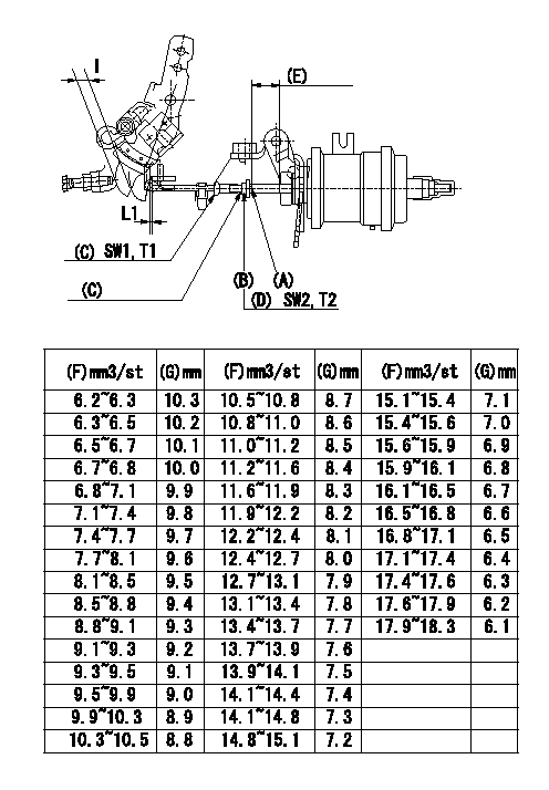
Adjustment of the two stage actuator (FICD).
1. Install the 2-stage actuator on the injection pump.
2. With the control lever in the idle position adjust using the rod position adjusting nut so that the clearance between control lever and the rod is L1.
3. Insert shim (thickness: l) determined from measured partial injection quantity between control lever and idle stopper. At this control lever position, adjust position of screw A so that actuator stroke becomes full stroke, Then fix using nut B.
Refer to table for thicknesses of actuator stroke adjusting shims from partial injection quantities
4. Table of actuator stroke adjusting shim thicknesses from partial injection quantity
At pump speed N1, insert a shim l2between the control lever and the idle stopper bolt and measure the injection quantity. Then, determine the shim thickness for actuator adjustment from the corresponding injection quantity in the table.
(C) Rod position adjusting nut
(D) Stroke adjusting nut
(E) Actuator stroke
(F) Injection quantity
(G) Shim thickness I
----------
L1=1+1(mm) N1=750(r/min) l2=8.1(mm)
----------
L1=1+1(mm) SW1=SW7 SW2=SW8 T1=1.4~2.0(Nm)(0.14~0.2(kgfm)) T2=3.4~4.9(Nm)(0.35~0.5(kgfm))
----------
L1=1+1(mm) N1=750(r/min) l2=8.1(mm)
----------
L1=1+1(mm) SW1=SW7 SW2=SW8 T1=1.4~2.0(Nm)(0.14~0.2(kgfm)) T2=3.4~4.9(Nm)(0.35~0.5(kgfm))
Information:
Start By:a. remove timing gear coverb. remove flywheel housingc. remove pistons and connecting rod assembliesd. remove crankshaft rear seal and wear sleevee. remove crankshaft front seal and wear sleeve Check the bearing caps for a number as to their location. If a number can not be seen, put a number on the left side of cylinder block and bearing cap. 1. Remove bolts (1) that hold main bearing caps (2) to the block, and remove main bearing caps (2). 2. Install one of the bolts from the front pulley in each end of the crankshaft.3. Fasten a hoist to crankshaft (3), and remove crankshaft (3) from the block. The weight is 159 kg (350 lb.). If new main bearings are not to be installed, keep old bearings with identification as to their location in cylinder block. 4. Use tooling (A) to remove the crankshaft gear.5. Use tooling (B) if necessary to remove the dowel and the pin.Install Crankshaft
If the crankshaft journals and bores for the block and rods were measured at disassembly and found to be within specifications, no further checks are necessary. However, if the serviceman still wants to measure the bearing clearances, Plastigage is recommended. Lead wire, shim stock or use of a dial bore gauge can damage the bearing surface.The serviceman must be very careful to use Plastigage, tool (B) correctly. The following points must be remembered:... Make sure that the backs of the bearings and the bores are clean and dry.... Make sure that the bearing locking tabs are properly seated in their slots.... The crankshaft must be free of oil where the Plastigage touches it.... If the main bearing clearances are checked with the engine upright or on its side, the crankshaft must be supported. Use a jack under an adjacent crankshaft counterweight and hold the crankshaft against the crown of the bearing. If the crankshaft is not supported, the weight of the crankshaft will cause incorrect readings.... Put a piece of Plastigage on the crown of the bearing half that is in the cap. Do not allow the Plastigage to extend over the edge of the bearing.... Install the bearing cap using the correct torque-turn specifications. Do not use an impact wrench. Be careful not to dislodge the bearing when the cap is installed.... Do not turn the crankshaft with the Plastigage installed.... Carefully remove the cap but do not remove the Plastigage. Measure the width of the Plastigage while it is in the bearing cap or on the crankshaft journal. Do this by using the correct scale on the package. Record the measurements.... Remove the Plastigage before reinstalling the cap.When using Plastigage, the readings can sometimes be unclear. For example, all parts of the Plastigage are not the same width. Measure the major widths to make sure that they are within the specification range. Also, experience has shown that when checking clearances tighter than 0.10 mm (.004") the readings may be low by 0.013 to 0.025 mm (.0005 to .0010"). Out-of-round
If the crankshaft journals and bores for the block and rods were measured at disassembly and found to be within specifications, no further checks are necessary. However, if the serviceman still wants to measure the bearing clearances, Plastigage is recommended. Lead wire, shim stock or use of a dial bore gauge can damage the bearing surface.The serviceman must be very careful to use Plastigage, tool (B) correctly. The following points must be remembered:... Make sure that the backs of the bearings and the bores are clean and dry.... Make sure that the bearing locking tabs are properly seated in their slots.... The crankshaft must be free of oil where the Plastigage touches it.... If the main bearing clearances are checked with the engine upright or on its side, the crankshaft must be supported. Use a jack under an adjacent crankshaft counterweight and hold the crankshaft against the crown of the bearing. If the crankshaft is not supported, the weight of the crankshaft will cause incorrect readings.... Put a piece of Plastigage on the crown of the bearing half that is in the cap. Do not allow the Plastigage to extend over the edge of the bearing.... Install the bearing cap using the correct torque-turn specifications. Do not use an impact wrench. Be careful not to dislodge the bearing when the cap is installed.... Do not turn the crankshaft with the Plastigage installed.... Carefully remove the cap but do not remove the Plastigage. Measure the width of the Plastigage while it is in the bearing cap or on the crankshaft journal. Do this by using the correct scale on the package. Record the measurements.... Remove the Plastigage before reinstalling the cap.When using Plastigage, the readings can sometimes be unclear. For example, all parts of the Plastigage are not the same width. Measure the major widths to make sure that they are within the specification range. Also, experience has shown that when checking clearances tighter than 0.10 mm (.004") the readings may be low by 0.013 to 0.025 mm (.0005 to .0010"). Out-of-round
Have questions with 104740-8190?
Group cross 104740-8190 ZEXEL
Mitsubishi
Mitsubishi
Mitsubishi
Mitsubishi
Mitsubishi
Mitsubishi
Mitsubishi
Mitsubishi
Mitsubishi
104740-8190
INJECTION-PUMP ASSEMBLY