Information injection-pump assembly
ZEXEL
104740-8170
1047408170
Rating:
Cross reference number
ZEXEL
104740-8170
1047408170
Zexel num
Bosch num
Firm num
Name
104740-8170
INJECTION-PUMP ASSEMBLY
Calibration Data:
Adjustment conditions
Test oil
1404 Test oil ISO4113orSAEJ967d
1404 Test oil ISO4113orSAEJ967d
Test oil temperature
degC
45
45
50
Nozzle
105000-2010
Bosch type code
NP-DN12SD12TT
Nozzle holder
105780-2080
Opening pressure
MPa
14.7
14.7
15.19
Opening pressure
kgf/cm2
150
150
155
Injection pipe
Inside diameter - outside diameter - length (mm) mm 2-6-840
Inside diameter - outside diameter - length (mm) mm 2-6-840
Transfer pump pressure
kPa
20
20
20
Transfer pump pressure
kgf/cm2
0.2
0.2
0.2
Direction of rotation (viewed from drive side)
Right R
Right R
Injection timing adjustment
Pump speed
r/min
750
750
750
Boost pressure
kPa
44
42.7
45.3
Boost pressure
mmHg
330
320
340
Average injection quantity
mm3/st.
64.8
64.3
65.3
Basic
*
Oil temperature
degC
50
48
52
Remarks
CBS
CBS
Injection timing adjustment_02
Pump speed
r/min
2000
2000
2000
Boost pressure
kPa
73.3
72
74.6
Boost pressure
mmHg
550
540
560
Average injection quantity
mm3/st.
65.5
65
66
Basic
*
Oil temperature
degC
50
48
52
Remarks
Full
Full
Injection timing adjustment_03
Pump speed
r/min
600
600
600
Boost pressure
kPa
0
0
0
Boost pressure
mmHg
0
0
0
Average injection quantity
mm3/st.
46
43.5
48.5
Oil temperature
degC
50
48
52
Injection timing adjustment_04
Pump speed
r/min
750
750
750
Boost pressure
kPa
44
42.7
45.3
Boost pressure
mmHg
330
320
340
Average injection quantity
mm3/st.
64.8
63.8
65.8
Basic
*
Oil temperature
degC
50
48
52
Remarks
CBS
CBS
Injection timing adjustment_05
Pump speed
r/min
1000
1000
1000
Boost pressure
kPa
73.3
72
74.6
Boost pressure
mmHg
550
540
560
Average injection quantity
mm3/st.
73
73
73
Oil temperature
degC
50
48
52
Injection timing adjustment_06
Pump speed
r/min
1250
1250
1250
Boost pressure
kPa
73.3
72
74.6
Boost pressure
mmHg
550
540
560
Average injection quantity
mm3/st.
69.2
66.7
71.7
Oil temperature
degC
50
48
52
Injection timing adjustment_07
Pump speed
r/min
2000
2000
2000
Boost pressure
kPa
73.3
72
74.6
Boost pressure
mmHg
550
540
560
Average injection quantity
mm3/st.
65.5
64.5
66.5
Difference in delivery
mm3/st.
5
Basic
*
Oil temperature
degC
50
48
52
Remarks
Full
Full
Injection timing adjustment_08
Pump speed
r/min
2100
2100
2100
Boost pressure
kPa
73.3
72
74.6
Boost pressure
mmHg
550
540
560
Average injection quantity
mm3/st.
63.8
62.3
65.3
Oil temperature
degC
52
50
54
Injection quantity adjustment
Pump speed
r/min
2650
2650
2650
Boost pressure
kPa
73.3
72
74.6
Boost pressure
mmHg
550
540
560
Average injection quantity
mm3/st.
25
22
28
Difference in delivery
mm3/st.
5.5
Basic
*
Oil temperature
degC
55
52
58
Injection quantity adjustment_02
Pump speed
r/min
3050
3050
3050
Boost pressure
kPa
73.3
72
74.6
Boost pressure
mmHg
550
540
560
Average injection quantity
mm3/st.
5
Oil temperature
degC
55
52
58
Injection quantity adjustment_03
Pump speed
r/min
2650
2650
2650
Boost pressure
kPa
73.3
72
74.6
Boost pressure
mmHg
550
540
560
Average injection quantity
mm3/st.
25
20
30
Difference in delivery
mm3/st.
5.5
Basic
*
Oil temperature
degC
55
52
58
Governor adjustment
Pump speed
r/min
375
375
375
Boost pressure
kPa
0
0
0
Boost pressure
mmHg
0
0
0
Average injection quantity
mm3/st.
12
10.5
13.5
Difference in delivery
mm3/st.
2
Basic
*
Oil temperature
degC
48
46
50
Governor adjustment_02
Pump speed
r/min
375
375
375
Boost pressure
kPa
0
0
0
Boost pressure
mmHg
0
0
0
Average injection quantity
mm3/st.
12
10
14
Difference in delivery
mm3/st.
2
Basic
*
Oil temperature
degC
48
46
50
Governor adjustment_03
Pump speed
r/min
750
750
750
Boost pressure
kPa
0
0
0
Boost pressure
mmHg
0
0
0
Average injection quantity
mm3/st.
3
Oil temperature
degC
50
48
52
Timer adjustment
Pump speed
r/min
100
100
100
Boost pressure
kPa
0
0
0
Boost pressure
mmHg
0
0
0
Average injection quantity
mm3/st.
63
63
83
Basic
*
Oil temperature
degC
48
46
50
Remarks
IDLE
IDLE
Timer adjustment_02
Pump speed
r/min
100
100
100
Boost pressure
kPa
0
0
0
Boost pressure
mmHg
0
0
0
Average injection quantity
mm3/st.
63
63
83
Oil temperature
degC
48
46
50
Speed control lever angle
Pump speed
r/min
375
375
375
Boost pressure
kPa
0
0
0
Boost pressure
mmHg
0
0
0
Average injection quantity
mm3/st.
0
0
0
Oil temperature
degC
48
46
50
Remarks
Magnet OFF at idling position
Magnet OFF at idling position
0000000901
Pump speed
r/min
1250
1250
1250
Boost pressure
kPa
73.3
72
74.6
Boost pressure
mmHg
550
540
560
Overflow quantity
cm3/min
420
290
550
Oil temperature
degC
50
48
52
Stop lever angle
Pump speed
r/min
1250
1250
1250
Boost pressure
kPa
73.3
72
74.6
Boost pressure
mmHg
550
540
560
Pressure
kPa
471
442
500
Pressure
kgf/cm2
4.8
4.5
5.1
Basic
*
Oil temperature
degC
50
48
52
Stop lever angle_02
Pump speed
r/min
600
600
600
Boost pressure
kPa
73.3
72
74.6
Boost pressure
mmHg
550
540
560
Pressure
kPa
314
275
353
Pressure
kgf/cm2
3.2
2.8
3.6
Oil temperature
degC
50
48
52
Stop lever angle_03
Pump speed
r/min
1250
1250
1250
Boost pressure
kPa
73.3
72
74.6
Boost pressure
mmHg
550
540
560
Pressure
kPa
471
432
510
Pressure
kgf/cm2
4.8
4.4
5.2
Basic
*
Oil temperature
degC
50
48
52
Stop lever angle_04
Pump speed
r/min
2100
2100
2100
Boost pressure
kPa
73.3
72
74.6
Boost pressure
mmHg
550
540
560
Pressure
kPa
667
628
706
Pressure
kgf/cm2
6.8
6.4
7.2
Oil temperature
degC
52
50
54
0000001101
Pump speed
r/min
1250
1250
1250
Boost pressure
kPa
73.3
72
74.6
Boost pressure
mmHg
550
540
560
Timer stroke
mm
3.7
3.5
3.9
Basic
*
Oil temperature
degC
50
48
52
_02
Pump speed
r/min
500
500
500
Boost pressure
kPa
73.3
72
74.6
Boost pressure
mmHg
550
540
560
Timer stroke
mm
1.2
0.6
1.8
Oil temperature
degC
48
46
50
_03
Pump speed
r/min
750
750
750
Boost pressure
kPa
73.3
72
74.6
Boost pressure
mmHg
550
540
560
Timer stroke
mm
2
1.4
2.6
Oil temperature
degC
50
48
52
_04
Pump speed
r/min
1250
1250
1250
Boost pressure
kPa
73.3
72
74.6
Boost pressure
mmHg
550
540
560
Timer stroke
mm
3.7
3.3
4.1
Basic
*
Oil temperature
degC
50
48
52
_05
Pump speed
r/min
1750
1750
1750
Boost pressure
kPa
73.3
72
74.6
Boost pressure
mmHg
550
540
560
Timer stroke
mm
5.8
5.2
6.4
Oil temperature
degC
50
48
52
_06
Pump speed
r/min
2100
2100
2100
Boost pressure
kPa
73.3
72
74.6
Boost pressure
mmHg
550
540
560
Timer stroke
mm
7.2
6.6
7.8
Oil temperature
degC
52
50
54
_07
Pump speed
r/min
2250
2250
2250
Boost pressure
kPa
73.3
72
74.6
Boost pressure
mmHg
550
540
560
Timer stroke
mm
7.8
7.4
8.2
Oil temperature
degC
52
50
54
0000001201
Max. applied voltage
V
8
8
8
Test voltage
V
13
12
14
0000001401
Pump speed
r/min
1250
1250
1250
Boost pressure
kPa
73.3
72
74.6
Boost pressure
mmHg
550
540
560
Average injection quantity
mm3/st.
53
52.5
53.5
Timer stroke TA
mm
3.1
3.1
3.1
Timer stroke variation dT
mm
0.6
0.4
0.8
Basic
*
Oil temperature
degC
50
48
52
_02
Pump speed
r/min
1250
1250
1250
Boost pressure
kPa
73.3
72
74.6
Boost pressure
mmHg
550
540
560
Average injection quantity
mm3/st.
53
52
54
Timer stroke variation dT
mm
0.6
0.2
1
Basic
*
Oil temperature
degC
50
48
52
_03
Pump speed
r/min
1250
1250
1250
Boost pressure
kPa
73.3
72
74.6
Boost pressure
mmHg
550
540
560
Average injection quantity
mm3/st.
40
39
41
Timer stroke variation dT
mm
1.4
0.9
1.9
Oil temperature
degC
50
48
52
Timing setting
K dimension
mm
3.3
3.2
3.4
KF dimension
mm
5.8
5.7
5.9
MS dimension
mm
0.7
0.6
0.8
BCS stroke
mm
6.5
6.4
6.6
Control lever angle alpha
deg.
59
55
63
Control lever angle beta
deg.
42
37
47
Test data Ex:
0000001801 POTENTIOMETER ADJUSTMENT
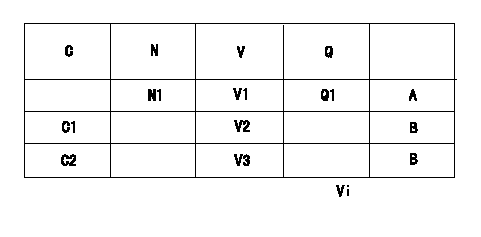
Adjustment of the potentiometer
Dummy bolt method
1. Hold the dummy bolt against the control lever at position N = N1 and Q = Q1 and fix using the lock nut.
2. At potentiometer adjustment, with the control lever contacting the dummy bolt, adjust the potentiometer so that the output voltage is V1.
3. After adjustment, remove the dummy bolt and confirm that the potentiometer output voltage at the control lever's idling and full speed positions is as specified above.
N:Pump speed
P:Boost pressure
Q:Injection quantity
V:Output voltage
A:Adjusting point
B:Checking point
C/L: control lever position
I:Idling
F:Full speed
Vi:Applied voltage
----------
----------
N1=750(r/min) V1=5+-0.03(V) V2=1++(V) V3=(8.6(V)) Q1=35.5+-1(mm3/st) Vi=10(V)
----------
----------
N1=750(r/min) V1=5+-0.03(V) V2=1++(V) V3=(8.6(V)) Q1=35.5+-1(mm3/st) Vi=10(V)
0000001901 V-FICD ADJUSTMENT
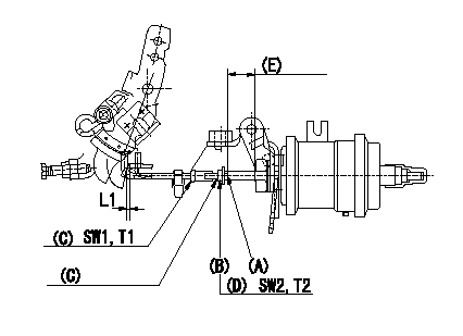
Adjustment of the two stage actuator (FICD).
1. Install the 2-stage actuator on the injection pump.
2. With the control lever in the idle position adjust using the rod position adjusting nut so that the clearance between control lever and the rod is L1.
3. After adjusting the potentiometer, fix the control lever so that the potentiometer output voltage is V1. (Applied voltage Vi)
4. Adjust the position of A so that the actuator stroke is the full stroke, then fix using nut (B).
(C) Rod position adjusting nut
(D) Stroke adjusting nut
(E) Actuator stroke
----------
L1=1+1(mm) V1=3.5+-0.03(V) Vi=10(V)
----------
L1=1+1(mm) SW1=SW7 SW2=SW8 T1=1.4~2.0(Nm)(0.14~0.2(kgfm)) T2=3.4~4.9(Nm)(0.35~0.5(kgfm))
----------
L1=1+1(mm) V1=3.5+-0.03(V) Vi=10(V)
----------
L1=1+1(mm) SW1=SW7 SW2=SW8 T1=1.4~2.0(Nm)(0.14~0.2(kgfm)) T2=3.4~4.9(Nm)(0.35~0.5(kgfm))
Information:
Start By:a. remove valve covers 1. Loosen the fuel injection line nut at the nozzle end with tool (A).2. Loosen the fuel line nut at the fuel injection line adapter with tool (B). Remove inner fuel injection lines (1). Install caps and plugs on all fuel line openings to keep dirt out of the fuel system. If necessary, use tooling (D) to turn the engine so the valves do not make contact with the pistons when the valves are opened with tool (C) to remove the push rods.3. Put compression on the valve springs with tool (C), and remove push rods (2). Put identification marks on the push rods as to their location in the engine.4. Push the push rod end of the rocker arms down. 5. Remove the intake valve lifter with tooling (E) as follows:a. Install 5P2685 Nut (3) and 5P6601 Collet (4) on 5P2408 Outer Handle Assembly (5).b. Install 5P6599 Inner Handle Assembly (6) in 5P2408 Outer Handle Assembly (5). c. Install tooling (E) in the intake valve lifter. Hold the 5P2408 Outer Handle Assembly, and tighten the 5P6599 Inner Handle Assembly until the 5P6601 Collet is tight against the inside of the intake valve lifter. d. Remove intake valve lifters (7) from the cylinder block with tooling (E). Put identification marks on the lifters as to their location in the engine. 6. Remove the exhaust valve lifters with tooling (E) as follows:a. Install 5P2685 Nut (3) and 5P6601 Collet (4) on 5P2408 Outer Handle Assembly (5). The opening in the cylinder head assembly for the intake valve lifter is larger than the opening in the exhaust valve lifter side. The tooling and each valve lifter must be installed and removed from the intake valve lifter side.b. Install the outer handle assembly in the intake valve lifter side of the cylinder head assembly. Slide the flat area of 5P2408 Outer Handle Assembly (5) through the head casting, and install the 5P6601 Collet in the exhaust valve lifters. c. Install 5P6599 Inner Handle Assembly (6) in 5P2408 Outer Handle Assembly (5). Hold the 5P2408 Handle Assembly, and tighten the 5P6599 Handle Assembly until the 5P6601 Collet is tight against the inside of the exhaust valve lifter.d. Pull the exhaust valve lifter up until the spring on the exhaust valve lifter is free from the cylinder block.e. Remove the 5P6599 Inner Handle Assembly. Slide the 5P2408 Outer Handle Assembly through the head casting, and remove it from the intake valve lifter side of the cylinder head. f. Use a magnet, and remove exhaust valve lifters (8) from the intake valve lifter side of the cylinder head assembly. Put identification marks on the lifters as to their location in the engine.7. Remove the guide springs from the lifters.Install Valve Lifters
Steps 1 and 2 must be done to install intake or exhaust valve lifters.
Make sure guide spring (9) is not damaged or worn. If the guide spring is damaged or worn, replace the guide spring. See Guideline For Reusable
Steps 1 and 2 must be done to install intake or exhaust valve lifters.
Make sure guide spring (9) is not damaged or worn. If the guide spring is damaged or worn, replace the guide spring. See Guideline For Reusable
Have questions with 104740-8170?
Group cross 104740-8170 ZEXEL
Mitsubishi
Mitsubishi
Mitsubishi
Mitsubishi
Mitsubishi
Mitsubishi
Mitsubishi
104740-8170
INJECTION-PUMP ASSEMBLY