Information injection-pump assembly
BOSCH
9 460 614 312
9460614312
ZEXEL
104740-7660
1047407660
NISSAN-DIESEL
1670021T17
1670021t17
Rating:
Cross reference number
BOSCH
9 460 614 312
9460614312
ZEXEL
104740-7660
1047407660
NISSAN-DIESEL
1670021T17
1670021t17
Zexel num
Bosch num
Firm num
Name
104740-7660
9 460 614 312
1670021T17 NISSAN-DIESEL
INJECTION-PUMP ASSEMBLY
TD25 * K
TD25 * K
Calibration Data:
Adjustment conditions
Test oil
1404 Test oil ISO4113orSAEJ967d
1404 Test oil ISO4113orSAEJ967d
Test oil temperature
degC
45
45
50
Nozzle
105000-2010
Bosch type code
NP-DN12SD12TT
Nozzle holder
105780-2080
Opening pressure
MPa
14.7
14.7
15.19
Opening pressure
kgf/cm2
150
150
155
Injection pipe
Inside diameter - outside diameter - length (mm) mm 2-6-840
Inside diameter - outside diameter - length (mm) mm 2-6-840
Transfer pump pressure
kPa
20
20
20
Transfer pump pressure
kgf/cm2
0.2
0.2
0.2
Direction of rotation (viewed from drive side)
Right R
Right R
(Solenoid timer adjustment condition)
OFF
Injection timing adjustment
Pump speed
r/min
1100
1100
1100
Average injection quantity
mm3/st.
45.8
45.3
46.3
Difference in delivery
mm3/st.
3
Basic
*
Injection timing adjustment_02
Pump speed
r/min
2500
2500
2500
Average injection quantity
mm3/st.
12.1
9.6
14.6
Injection timing adjustment_03
Pump speed
r/min
2300
2300
2300
Average injection quantity
mm3/st.
32.8
28.3
37.3
Injection timing adjustment_04
Pump speed
r/min
2150
2150
2150
Average injection quantity
mm3/st.
37.9
35.8
40
Injection timing adjustment_05
Pump speed
r/min
1100
1100
1100
Average injection quantity
mm3/st.
45.8
44.8
46.8
Injection timing adjustment_06
Pump speed
r/min
600
600
600
Average injection quantity
mm3/st.
44.4
42.4
46.4
Injection quantity adjustment
Pump speed
r/min
2500
2500
2500
Average injection quantity
mm3/st.
12.1
10.1
14.1
Basic
*
Injection quantity adjustment_02
Pump speed
r/min
2700
2700
2700
Average injection quantity
mm3/st.
5
Governor adjustment
Pump speed
r/min
350
350
350
Average injection quantity
mm3/st.
6.5
4.5
8.5
Difference in delivery
mm3/st.
2
Basic
*
Governor adjustment_02
Pump speed
r/min
350
350
350
Average injection quantity
mm3/st.
6.5
4.5
8.5
Governor adjustment_03
Pump speed
r/min
450
450
450
Average injection quantity
mm3/st.
3
Timer adjustment
Pump speed
r/min
100
100
100
Average injection quantity
mm3/st.
62.5
45
80
Basic
*
Speed control lever angle
Pump speed
r/min
350
350
350
Average injection quantity
mm3/st.
0
0
0
Remarks
Magnet OFF
Magnet OFF
0000000901
Pump speed
r/min
1100
1100
1100
Overflow quantity with S/T ON
cm3/min
390
258
522
_02
Pump speed
r/min
1100
1100
1100
Overflow quantity with S/T ON
cm3/min
489
360
618
Remarks
Without an O-ring
Without an O-ring
Stop lever angle
Pump speed
r/min
1100
1100
1100
Pressure with S/T ON
kPa
480.5
441
520
Pressure with S/T ON
kgf/cm2
4.9
4.5
5.3
Pressure with S/T OFF
kPa
372.5
343
402
Pressure with S/T OFF
kgf/cm2
3.8
3.5
4.1
Basic
*
Stop lever angle_02
Pump speed
r/min
1100
1100
1100
Pressure with S/T ON
kPa
480.5
441
520
Pressure with S/T ON
kgf/cm2
4.9
4.5
5.3
Pressure with S/T OFF
kPa
372.5
343
402
Pressure with S/T OFF
kgf/cm2
3.8
3.5
4.1
Stop lever angle_03
Pump speed
r/min
1700
1700
1700
Pressure with S/T OFF
kPa
510
481
539
Pressure with S/T OFF
kgf/cm2
5.2
4.9
5.5
Stop lever angle_04
Pump speed
r/min
2150
2150
2150
Pressure with S/T OFF
kPa
598.5
569
628
Pressure with S/T OFF
kgf/cm2
6.1
5.8
6.4
0000001101
Pump speed
r/min
1100
1100
1100
Timer stroke with S/T ON
mm
4.3
3.9
4.7
Timer stroke with S/T OFF
mm
2.6
2.4
2.8
Basic
*
_02
Pump speed
r/min
1100
1100
1100
Timer stroke with S/T ON
mm
4.3
3.8
4.8
Timer stroke with S/T OFF
mm
2.6
2.3
2.9
_03
Pump speed
r/min
1700
1700
1700
Timer stroke with S/T OFF
mm
4.9
4.3
5.5
_04
Pump speed
r/min
2300
2300
2300
Timer stroke with S/T OFF
mm
6.5
6
7
0000001201
Max. applied voltage
V
8
8
8
Test voltage
V
13
12
14
Timing setting
K dimension
mm
3.3
3.2
3.4
KF dimension
mm
5.8
5.7
5.9
MS dimension
mm
1
0.9
1.1
Control lever angle alpha
deg.
54
50
58
Control lever angle beta
deg.
36
31
41
Test data Ex:
0000001801 CONTROL LEVER ANGLE
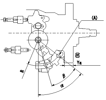
Control lever angle measurement
1. Measure dimension L between the end of the lever and the flange face.
2. Measure the lever angle from the pin hole R (plate).
(A) = lever angle measuring position
(B) = flange face
----------
L=10.7~14.2mm R=49mm
----------
L=10.7~14.2mm R=49mm
----------
L=10.7~14.2mm R=49mm
----------
L=10.7~14.2mm R=49mm
Information:
Start By:a. remove cylinder headb. remove oil panc. remove cooling jets 1. Remove two rod cap bolts (1) from each rod. Remove rod caps (2).2. Using a soft hammer tape rod (3) away from crankshaft and remove bearing half (4). When removing cylinder pack, watch the rod and prevent it from catching on the block bore as it comes out.3. Install tooling (A) and remove cylinder pack (5). 4. Remove cylinder liner seal (6) at the base of the spacer block. 5. Remove the remainder of tooling (A) from cylinder pack (5) and then remove the rod and piston from the cylinder liner. The following steps are for the installation of the cylinder pack.6. Install a new cylinder liner seal, lubricate the seal with engine oil. Some engines use pistons which have the word "FRONT" stamped on the crown of the piston. Make sure the word "FRONT" is toward the front of the engine when the piston is installed. The etched number on the connecting rod must be on the right side and must be installed in the corresponding cylinder. 9U-5839 Liquid Gasket Material is applied to the cylinder liners in the area shown in the illustration. The liquid gasket material helps prevent oil leaks from between the cylinder block and spacer block. DO NOT apply any 9U-5839 Liquid Gasket Material between the engine spacer block and the cylinder block surfaces. Using excessive amounts of liquid gasket material on the liner flange seat can cause oil leaks due to distortion of the O-ring seals between the spacer block and cylinder block.7. Lubricate the lower portion of the cylinder liner with engine oil. Be sure the corresponding crankshaft throw is at bottom center. Position cylinder pack (5) and guide rod (3) into place. Use tooling (B) and press cylinder pack (5) into place.8. With rod (3) in this position, install the upper half of rod bearing (4). Be sure the bearing tab properly engages the slot in the connecting rod. Lubricate the bearing surface with engine oil and tap the piston down with a rubber mallet until the rod and bearing contacts the crankshaft.9. With rod cap bearing in place and oiled, install rod cap (2). Lubricate rod bolts (1) with 2P2506 Thread Lubricant. Install rod bolts (1) and torque to 130 7 N m (95 5 lb.ft.). Mark each bolt head and then tighten each bolt an additional 60 5° (1/6 turn).End By:a. install cooling jets.b. install oil pan.c. install cylinder head.
Have questions with 104740-7660?
Group cross 104740-7660 ZEXEL
Dpico
Nissan-Diesel
Dpico
Nissan-Diesel
104740-7660
9 460 614 312
1670021T17
INJECTION-PUMP ASSEMBLY
TD25
TD25