Information injection-pump assembly
BOSCH
9 460 620 022
9460620022
ZEXEL
104740-6130
1047406130
ISUZU
8971433270
8971433270
Rating:
Cross reference number
BOSCH
9 460 620 022
9460620022
ZEXEL
104740-6130
1047406130
ISUZU
8971433270
8971433270
Zexel num
Bosch num
Firm num
Name
104740-6130
9 460 620 022
8971433270 ISUZU
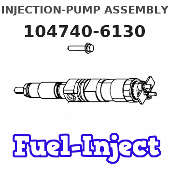
INJECTION-PUMP ASSEMBLY
4EE1 * K
4EE1 * K
Calibration Data:
Adjustment conditions
Test oil
1404 Test oil ISO4113orSAEJ967d
1404 Test oil ISO4113orSAEJ967d
Test oil temperature
degC
45
45
50
Nozzle
105780-0060
Bosch type code
NP-DN0SD1510
Nozzle holder
105780-2150
Opening pressure
MPa
13
13
13.3
Opening pressure
kgf/cm2
133
133
136
Injection pipe
157805-7320
Injection pipe
Inside diameter - outside diameter - length (mm) mm 2-6-450
Inside diameter - outside diameter - length (mm) mm 2-6-450
Joint assembly
157641-4720
Tube assembly
157641-4020
Transfer pump pressure
kPa
20
20
20
Transfer pump pressure
kgf/cm2
0.2
0.2
0.2
Direction of rotation (viewed from drive side)
Right R
Right R
Injection timing adjustment
Pump speed
r/min
1325
1325
1325
Average injection quantity
mm3/st.
34.9
34.4
35.4
Difference in delivery
mm3/st.
3.5
Basic
*
Injection timing adjustment_02
Pump speed
r/min
400
400
400
Average injection quantity
mm3/st.
37.7
33.7
41.7
Injection timing adjustment_03
Pump speed
r/min
510
510
510
Average injection quantity
mm3/st.
34.3
31.5
37.1
Injection timing adjustment_04
Pump speed
r/min
600
600
600
Average injection quantity
mm3/st.
33.3
30.5
36.1
Injection timing adjustment_05
Pump speed
r/min
1325
1325
1325
Average injection quantity
mm3/st.
34.9
33.9
35.9
Difference in delivery
mm3/st.
3.5
Basic
*
Injection timing adjustment_06
Pump speed
r/min
1750
1750
1750
Average injection quantity
mm3/st.
35.6
33.6
37.6
Injection timing adjustment_07
Pump speed
r/min
2200
2200
2200
Average injection quantity
mm3/st.
35.3
33.3
37.3
Injection quantity adjustment
Pump speed
r/min
2600
2600
2600
Average injection quantity
mm3/st.
17.1
14.1
20.1
Difference in delivery
mm3/st.
5
Basic
*
Injection quantity adjustment_02
Pump speed
r/min
2400
2400
2400
Average injection quantity
mm3/st.
34.3
28.8
37.8
Injection quantity adjustment_03
Pump speed
r/min
2600
2600
2600
Average injection quantity
mm3/st.
17.1
13.6
20.6
Difference in delivery
mm3/st.
5
Basic
*
Injection quantity adjustment_04
Pump speed
r/min
2800
2800
2800
Average injection quantity
mm3/st.
5
Governor adjustment
Pump speed
r/min
435
435
435
Average injection quantity
mm3/st.
12.5
10.5
14.5
Difference in delivery
mm3/st.
2
Basic
*
Governor adjustment_02
Pump speed
r/min
435
435
435
Average injection quantity
mm3/st.
12.5
10.5
14.5
Difference in delivery
mm3/st.
2
Basic
*
Governor adjustment_03
Pump speed
r/min
620
620
620
Average injection quantity
mm3/st.
5
Timer adjustment
Pump speed
r/min
100
100
100
Average injection quantity
mm3/st.
51.5
41.5
61.5
Basic
*
Remarks
IDLE
IDLE
Timer adjustment_02
Pump speed
r/min
100
100
100
Average injection quantity
mm3/st.
51.5
41.5
61.5
Remarks
IDLE
IDLE
Speed control lever angle
Pump speed
r/min
435
435
435
Average injection quantity
mm3/st.
0
0
0
Remarks
Magnet OFF at idling position
Magnet OFF at idling position
0000000901
Pump speed
r/min
1250
1250
1250
Overflow quantity
cm3/min
600
470
730
Stop lever angle
Pump speed
r/min
1250
1250
1250
Pressure
kPa
392
372
412
Pressure
kgf/cm2
4
3.8
4.2
Basic
*
Stop lever angle_02
Pump speed
r/min
850
850
850
Pressure
kPa
284
255
313
Pressure
kgf/cm2
2.9
2.6
3.2
Basic
*
Stop lever angle_03
Pump speed
r/min
1250
1250
1250
Pressure
kPa
392
372
412
Pressure
kgf/cm2
4
3.8
4.2
Stop lever angle_04
Pump speed
r/min
2100
2100
2100
Pressure
kPa
618
579
657
Pressure
kgf/cm2
6.3
5.9
6.7
0000001101
Pump speed
r/min
1250
1250
1250
Timer stroke
mm
2.6
2.4
2.8
Basic
*
_02
Pump speed
r/min
850
850
850
Timer stroke
mm
0.5
0.1
1.5
_03
Pump speed
r/min
1250
1250
1250
Timer stroke
mm
2.6
2.3
2.9
Basic
*
_04
Pump speed
r/min
1750
1750
1750
Timer stroke
mm
5
4.4
5.6
_05
Pump speed
r/min
2100
2100
2100
Timer stroke
mm
6.2
5.8
6.6
0000001201
Max. applied voltage
V
8
8
8
Test voltage
V
13
12
14
0000001401
Pump speed
r/min
1250
1250
1250
Average injection quantity
mm3/st.
22.7
21.7
23.7
Timer stroke TA
mm
2.3
2.3
2.3
Timer stroke variation dT
mm
0.3
0.1
0.5
Basic
*
_02
Pump speed
r/min
1250
1250
1250
Average injection quantity
mm3/st.
22.7
21.2
24.2
Timer stroke TA
mm
2.3
2.3
2.3
Timer stroke variation dT
mm
0.3
0
0.6
Basic
*
_03
Pump speed
r/min
1250
1250
1250
Average injection quantity
mm3/st.
10.8
9.3
12.3
Timer stroke TA
mm
1.5
1.5
1.5
Timer stroke variation dT
mm
1.1
0.6
1.6
Timing setting
K dimension
mm
3.3
3.2
3.4
KF dimension
mm
5.3
5.2
5.4
MS dimension
mm
0.8
0.7
0.9
Pre-stroke
mm
0.1
0.08
0.12
Control lever angle alpha
deg.
20
16
24
Control lever angle beta
deg.
44
40
48
Test data Ex:
0000001801 POTENTIOMETER ADJUSTMENT
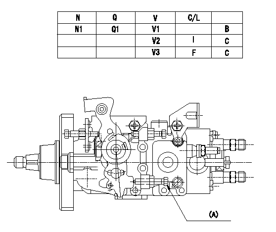
Adjustment of the potentiometer
Adjustment method (supply voltage Vi, dummy bolt method)
1. Hold the dummy bolt (A) against the control lever at position N = N1 and Q = Q1 and fix using the lock nut.
2. When adjusting the potentiometer, position the control lever against the dummy bolt (A) and adjust so that the output voltage is V1.
3. After adjustment, remove the dummy bolt and confirm that the potentiometer output voltage at the control lever's idling and full positions is as specified in the table.
(A) Dummy bolt
N:Pump speed
V:Output voltage
Q:Injection quantity
C/L: control lever position
I:Idling lever position
F:Full speed lever position
B:Adjusting point
C:Checking point
----------
N1=1000r/min V1=4.95+-0.03V Q1=17.3~19.3mm3/st
----------
N1=1000r/min Q1=17.3~19.3mm3/st V1=4.95+-0.03V V2=1.80+-0.45V V3=9.13+-0.65V
----------
N1=1000r/min V1=4.95+-0.03V Q1=17.3~19.3mm3/st
----------
N1=1000r/min Q1=17.3~19.3mm3/st V1=4.95+-0.03V V2=1.80+-0.45V V3=9.13+-0.65V
0000001901 W-CSD ADJUSTMENT
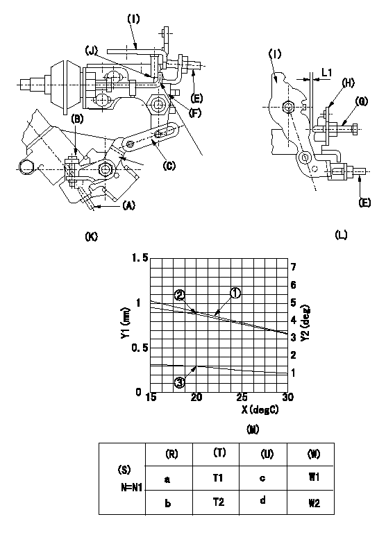
Adjustment of the W-CSD
1. Adjustment of the timer stroke
Adjust using screw (A) so that the timer stroke is the value determined using the graph (M). [(K), (M)]
2. Adjustment of the position of the intermediate lever.
Insert the shim (L1) between the control lever (I) and the idle set screw (G).
Align the intermediate lever (F) with the aligning mark (J) and fix the intermediate lever screw (E) so that it contacts the control lever. [(K), (L)]
3. Adjustment of the FICD
Insert the shim (L2) between the control lever (I) and the idle set screw (G).
Fix with the adjusting screw to the position where the CSD lever (C) actuates the intermediate lever through the rod (D). (K), (L), (M)
(O) Timer stroke adjustment (mm) - (1):TA = -0.0235t+1.37 (-20 deg <= t <=60 deg C)
(P) Lever position (deg) 2:theta 1 = -0.0625t+5.65 (-20 deg C <= t <= 20 deg C)
Theta 2 = -0.1108t + 6.62 (20 deg C =< t =< 60 deg C)
(Q) lever position (mm) 3: L1 = -0.02075t+1.878 (-20 deg C <= t <= 20 deg C)
L2 = -0.03900t + 2.277 (20 deg C =< t =< 60 deg C)
The (Q) indicates the clearance between the control lever and the idle set screw.
(R) Cooling water temperature (deg C)
(S) Cooling water temperature: increase direction
N:Pump speed
X:Temperature t (deg C)
Y1:Timer stroke TA (mm)
Y2:Control lever position at theta L (deg, mm)
(T) Timer piston stroke (mm)
(U) Lever position (deg)
(W) Lever position (mm)
----------
L1=2.1+-0.05mm L2=L1+-0.05mm
----------
N1=500r/min a=20degC b=-20degC c=4.4+-1deg d=6.9+-3deg T1=0.9+-0.4mm T2=1.8+-0.5mm W1=1.5+-0.3mm W2=2.3+-1mm
----------
L1=2.1+-0.05mm L2=L1+-0.05mm
----------
N1=500r/min a=20degC b=-20degC c=4.4+-1deg d=6.9+-3deg T1=0.9+-0.4mm T2=1.8+-0.5mm W1=1.5+-0.3mm W2=2.3+-1mm
Information:
Failure to follow these oil recommendations can cause shortened engine life due to deposits and or excessive wear.
Total Base Number (TBN) and Fuel Sulfur Levels For Caterpillar Prechamber Combustion (PC) Diesel Engines
New engine oil must have a TBN of 20 times (for Precombustion Chamber engines) and ten times (for direct injection engines) the percent fuel sulfur as measured by ASTM D2896 method. Refer to the following chart.
Y=oil TBN shown by ASTM D2896. X=percent of fuel sulfur by weight. New oil TBN (1). Change oil when the used oil TBN limit (2) is reached.Caterpillar's 20 times rule for TBN (Reference: Oil and Your Engine, SEBD0640) versus fuel sulfur was a general requirement developed in the early 1980's for Cat prechamber combustion (PC) system engines. Caterpillar still maintains 20 times TBN value for PC engines when using API CE or CF-4 oil (related to fuel sulfur above 0.5 percent). Engines built prior to 1990 can continue to use single grade viscosity oil or commercial oils, provided the engine operates to user satisfaction.Fuel sulfur neutralization of new oil formulations in direct injection (DI) system engines are more effective. Field results indicate that direct injection combustion (DI) systems and the oils now recommended for those engines will operate at an oil TBN equal to ten times the fuel sulfur.Total Base Number (TBN) and Fuel Sulfur Levels For Caterpillar Direct Injection (DI) Diesel Engines
The TBN for a new oil is dependent on the sulfur level of the fuel used. For direct injection engines running distillate diesel fuel, the minimum new oil TBN (by ASTM D 2896) must be 10 times the fuel sulfur level, and the minimum TBN is 5 regardless of sulfur level, see the chart below.TBN vs Fuel Sulfur for Caterpillar DI Diesel Engines
Y=oil TBN shown by ASTM D2896. X=percent of fuel sulfur by weight. New oil TBN (1). Change oil when the used oil TBN limit (2) is reached.In areas where the fuel sulfur exceeds 1.5 percent, choose an oil with the highest TBN that is within the API CF-4 or CG-4 categories, and shorten the oil change period based on oil analysis. The oil analysis should evaluate oil condition and wear metals. High TBN oils that are not within the API CF-4 or CG-4 categories can produce excessive piston deposits leading to a loss of oil control and bore polishing.
Operation at fuel sulfur levels over 1.5 percent may require shortened oil change periods to maintain adequate wear protection.
Lubricant Viscosity Recommendations
The proper SAE viscosity grade oil is determined by the minimum outside temperature at cold engine start up, and the maximum outside temperature during engine operation. Use the minimum temperature column on the chart to determine the oil viscosity required for starting a "cold soaked" engine. Use the maximum temperature column on the chart to select the viscosity for operation at the highest temperature anticipated. In general, use the highest viscosity oil available that still meets the start up temperature requirements. Synthetic Base Stock Oils
Synthetic base stock oils are acceptable
Have questions with 104740-6130?
Group cross 104740-6130 ZEXEL
Isuzu
104740-6130
9 460 620 022
8971433270
INJECTION-PUMP ASSEMBLY
4EE1
4EE1