Information injection-pump assembly
ZEXEL
104740-6080
1047406080

Rating:
Cross reference number
ZEXEL
104740-6080
1047406080
Zexel num
Bosch num
Firm num
Name
104740-6080
INJECTION-PUMP ASSEMBLY
Calibration Data:
Adjustment conditions
Test oil
1404 Test oil ISO4113orSAEJ967d
1404 Test oil ISO4113orSAEJ967d
Test oil temperature
degC
45
45
50
Nozzle
105780-0060
Bosch type code
NP-DN0SD1510
Nozzle holder
105780-2150
Opening pressure
MPa
13
13
13.3
Opening pressure
kgf/cm2
133
133
136
Injection pipe
157805-7320
Injection pipe
Inside diameter - outside diameter - length (mm) mm 2-6-450
Inside diameter - outside diameter - length (mm) mm 2-6-450
Joint assembly
157641-4720
Tube assembly
157641-4020
Transfer pump pressure
kPa
20
20
20
Transfer pump pressure
kgf/cm2
0.2
0.2
0.2
Direction of rotation (viewed from drive side)
Right R
Right R
Injection timing adjustment
Pump speed
r/min
1300
1300
1300
Average injection quantity
mm3/st.
37.2
36.7
37.7
Difference in delivery
mm3/st.
3.5
Basic
*
Oil temperature
degC
50
48
52
Injection timing adjustment_02
Pump speed
r/min
500
500
500
Average injection quantity
mm3/st.
37.7
33.7
41.7
Oil temperature
degC
48
46
50
Injection timing adjustment_03
Pump speed
r/min
600
600
600
Average injection quantity
mm3/st.
37.5
34.5
40.5
Oil temperature
degC
50
48
52
Injection timing adjustment_04
Pump speed
r/min
1300
1300
1300
Average injection quantity
mm3/st.
37.2
36.2
38.2
Difference in delivery
mm3/st.
3.5
Basic
*
Oil temperature
degC
50
48
52
Injection timing adjustment_05
Pump speed
r/min
2250
2250
2250
Average injection quantity
mm3/st.
37.6
35.6
39.6
Oil temperature
degC
52
50
54
Injection quantity adjustment
Pump speed
r/min
2600
2600
2600
Average injection quantity
mm3/st.
17.1
14.1
20.1
Difference in delivery
mm3/st.
5
Basic
*
Oil temperature
degC
55
52
58
Injection quantity adjustment_02
Pump speed
r/min
2800
2800
2800
Average injection quantity
mm3/st.
5
Oil temperature
degC
55
52
58
Injection quantity adjustment_03
Pump speed
r/min
2600
2600
2600
Average injection quantity
mm3/st.
17.1
14.1
20.1
Difference in delivery
mm3/st.
5
Basic
*
Oil temperature
degC
55
52
58
Governor adjustment
Pump speed
r/min
435
435
435
Average injection quantity
mm3/st.
12.5
10.5
14.5
Difference in delivery
mm3/st.
2
Basic
*
Oil temperature
degC
48
46
50
Governor adjustment_02
Pump speed
r/min
435
435
435
Average injection quantity
mm3/st.
12.5
10.5
14.5
Difference in delivery
mm3/st.
2
Basic
*
Oil temperature
degC
48
46
50
Timer adjustment
Pump speed
r/min
100
100
100
Average injection quantity
mm3/st.
51.5
41.5
61.5
Basic
*
Oil temperature
degC
48
46
50
Remarks
IDLE
IDLE
Timer adjustment_02
Pump speed
r/min
100
100
100
Average injection quantity
mm3/st.
51.5
41.5
61.5
Oil temperature
degC
48
46
50
Speed control lever angle
Pump speed
r/min
435
435
435
Average injection quantity
mm3/st.
0
0
0
Oil temperature
degC
48
46
50
Remarks
Magnet OFF at idling position
Magnet OFF at idling position
0000000901
Pump speed
r/min
1250
1250
1250
Overflow quantity
cm3/min
620
490
750
Oil temperature
degC
50
48
52
Stop lever angle
Pump speed
r/min
1250
1250
1250
Pressure
kPa
392
372
412
Pressure
kgf/cm2
4
3.8
4.2
Basic
*
Oil temperature
degC
50
48
52
Stop lever angle_02
Pump speed
r/min
1250
1250
1250
Pressure
kPa
392
372
412
Pressure
kgf/cm2
4
3.8
4.2
Basic
*
Oil temperature
degC
50
48
52
Stop lever angle_03
Pump speed
r/min
2100
2100
2100
Pressure
kPa
608
569
647
Pressure
kgf/cm2
6.2
5.8
6.6
Oil temperature
degC
52
50
54
0000001101
Pump speed
r/min
1250
1250
1250
Timer stroke
mm
2.6
2.4
2.8
Basic
*
Oil temperature
degC
50
48
52
_02
Pump speed
r/min
850
850
850
Timer stroke
mm
0.5
0.1
1.3
Oil temperature
degC
50
48
52
_03
Pump speed
r/min
1250
1250
1250
Timer stroke
mm
2.6
2.4
2.8
Basic
*
Oil temperature
degC
50
48
52
_04
Pump speed
r/min
1750
1750
1750
Timer stroke
mm
5
4.6
5.4
Oil temperature
degC
50
48
52
_05
Pump speed
r/min
2100
2100
2100
Timer stroke
mm
6.2
5.9
6.6
Oil temperature
degC
52
50
54
0000001201
Max. applied voltage
V
8
8
8
Test voltage
V
13
12
14
0000001401
Pump speed
r/min
1250
1250
1250
Average injection quantity
mm3/st.
22.2
21.2
23.2
Timer stroke TA
mm
2.2
2.2
2.2
Timer stroke variation dT
mm
0.4
0.2
0.6
Basic
*
Oil temperature
degC
50
48
52
_02
Pump speed
r/min
1250
1250
1250
Average injection quantity
mm3/st.
22.2
21.2
23.2
Timer stroke variation dT
mm
0.4
0.2
0.6
Basic
*
Oil temperature
degC
50
48
52
_03
Pump speed
r/min
1250
1250
1250
Average injection quantity
mm3/st.
10.8
9.8
11.8
Timer stroke variation dT
mm
1
0.6
1.4
Oil temperature
degC
50
48
52
Timing setting
K dimension
mm
3.3
3.2
3.4
KF dimension
mm
5.3
5.2
5.4
MS dimension
mm
0.7
0.6
0.8
Pre-stroke
mm
0.1
0.08
0.12
Control lever angle alpha
deg.
20
16
24
Control lever angle beta
deg.
45
40
50
Test data Ex:
0000001801 POTENTIOMETER ADJUSTMENT
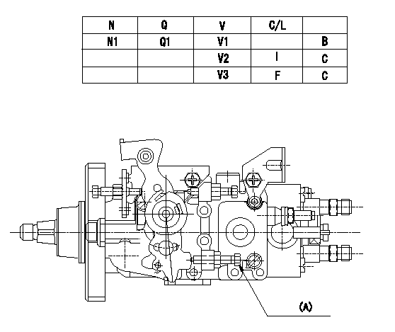
Adjustment of the potentiometer
Adjustment method (supply voltage Vi, dummy bolt method)
1. Hold the dummy bolt (A) against the control lever at position N = N1 and Q = Q1 and fix using the lock nut.
2. When adjusting the potentiometer, position the control lever against the dummy bolt (A) and adjust so that the output voltage is V1.
3. After adjustment, remove the dummy bolt and confirm that the potentiometer output voltage at the control lever's idling and full positions is as specified in the table.
(A) Dummy bolt
N:Pump speed
V:Output voltage
Q:Injection quantity
C/L: control lever position
I:Idling lever position
F:Full speed lever position
B:Adjusting point
C:Checking point
----------
N1=1000r/min Q1=18.3+-1.0mm3/st V1=4.95+-0.03V Vi=10V
----------
N1=1000r/min V1=4.95+-0.03V V2=(2.00+-0.45V) V3=(9.39+-0.65V) Q1=18.3+-1.0mm3/st
----------
N1=1000r/min Q1=18.3+-1.0mm3/st V1=4.95+-0.03V Vi=10V
----------
N1=1000r/min V1=4.95+-0.03V V2=(2.00+-0.45V) V3=(9.39+-0.65V) Q1=18.3+-1.0mm3/st
0000001901 W-CSD ADJUSTMENT
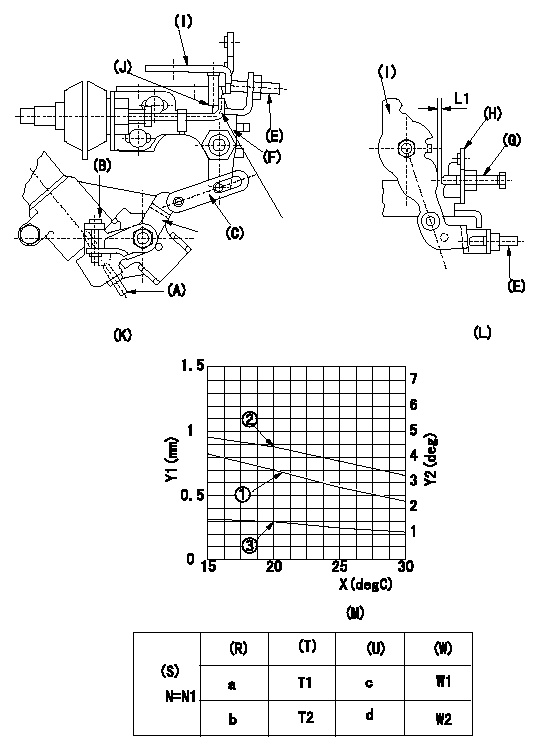
Adjustment of the W-CSD
1. Adjustment of the timer stroke
Adjust using screw (A) so that the timer stroke is the value determined using the graph (M). [(K), (M)]
2. Adjustment of the position of the intermediate lever.
Insert the shim (L1) between the control lever (I) and the idle set screw (G).
Align the intermediate lever (F) with the aligning mark (J) and fix the intermediate lever screw (E) so that it contacts the control lever. [(K), (L)]
3. Adjustment of the FICD
Insert the shim (L2) between the control lever (I) and the idle set screw (G).
Fix with the adjusting screw to the position where the CSD lever (C) actuates the intermediate lever through the rod (D). (K), (L), (M)
(O) timer stroke adjustment (mm) - (1): TA = -0.0235t + 1.17
(P) Lever angle (deg) - (2): Theta 1 = -0.0625 t + 5.65 (-20 deg C <= t <= 20 deg C)
Theta 2 = -0.1108t + 6.62 (20 deg C =< t =< 60 deg C)
(Q) lever position (mm) - (3): L1 = -0.02075t + 1.878 (-20 deg C <= t <= 20 deg C)
L2 = -0.03900t + 2.277 (20 deg C =< t =< 60 deg C)
The (Q) indicates the clearance between the control lever and the idle set screw.
(R): cooling water temperature (deg C)
(S): cooling water temperature: increase direction
N:Pump speed
X:Temperature t (deg C)
Y1:Timer stroke TA (mm)
Y2:Control lever position at theta L (deg, mm)
(T): Timer piston stroke (mm)
(U): Lever angle (deg)
(W): Lever position (mm)
----------
L1=2.0+-0.05mm L2=L1+-0.05mm
----------
N1=500r/min a=20degC b=-20degC c=4.4deg+-1deg d=6.9deg+-3deg T1=0.7+-0.2mm T2=1.6+-0.4mm W1=1.5+-0.3mm W2=2.3+-1mm L1=2.0+-0.05mm
----------
L1=2.0+-0.05mm L2=L1+-0.05mm
----------
N1=500r/min a=20degC b=-20degC c=4.4deg+-1deg d=6.9deg+-3deg T1=0.7+-0.2mm T2=1.6+-0.4mm W1=1.5+-0.3mm W2=2.3+-1mm L1=2.0+-0.05mm
Information:
Oils
Hot oil and components can cause personal injury. Do not allow hot oil or components to contact the skin.Keep all exhaust manifold and turbocharger shields in place to protect hot exhaust from oil spray in the event of a line, tube or seal failure.Batteries
Battery electrolyte contains acid and can cause injury. Avoid contact with the skin and eyes.Wash hands after touching batteries and connectors. Use of gloves is recommended.Batteries give off flammable fumes which can explode. Ensure there is proper ventilation for batteries which are located in an enclosure.Always thaw a frozen battery before jump starting. Frozen batteries can explode.Do not smoke when observing battery electrolyte levels.Always wear protective glasses when working with batteries.Never disconnect any charging unit circuit or battery circuit cable from the battery when charging unit is operating. A spark can cause the flammable vapor mixture of hydrogen and oxygen to explode.Fire or Explosion Prevention
Fire may result from lubricating oil or fuel sprayed on hot surfaces causing personal injury and property damage. Inspect all lines and tubes for wear or deterioration. They must be routed, supported or clamped securely. Tighten all connections to the recommended torque. Leaks can cause fires.Determine whether the engine will be operated in an environment in which combustible gases could be drawn through the air inlet system. These gases could cause the engine to overspeed, which in turn could seriously damage the engine and result in bodily injury or property damage.If your application involves the presence of combustible gases, consult your Caterpillar dealer to obtain additional information concerning protection devices (i.e. air inlet shutoff) suitable for the application involved.All fuels, most lubricants and some coolant mixtures are flammable.Diesel fuel is flammable. Gasoline is flammable. The mixture of diesel and gasoline fumes is extremely explosive.Do not smoke while refueling or in a refueling area.Do not smoke in areas where batteries are charged, or where flammable materials are stored.Batteries give off flammable fumes which can explode.Keep all fuels and lubricants stored in properly marked containers and away from all unauthorized persons.Store all oily rags or other flammable material in a protective container, in a safe place.Do not weld or flame cut on pipes or tubes that contain flammable fluids. Clean them thoroughly with nonflammable solvent before welding or flame cutting on them.Remove all flammable materials such as fuel, oil and other debris before they accumulate on the engine.Do not expose the engine to flames, burning brush, etc., if at all possible.Shields (if equipped), which protect hot exhaust components from oil or fuel spray in the event of a line, tube or seal failure, must be installed correctly.Provide adequate and proper waste oil disposal. Oil and fuel filters must be properly installed and housing covers tightened to proper torque when being changed.Batteries must be kept clean, covers kept on all cells, recommended cables and connections used and battery box covers kept in place when operating.When starting from an external source, always connect the positive (+) jumper cable to the POSITIVE (+) terminal of the
Have questions with 104740-6080?
Group cross 104740-6080 ZEXEL
Isuzu
Isuzu
104740-6080
INJECTION-PUMP ASSEMBLY