Information injection-pump assembly
ZEXEL
104740-4790
1047404790

Rating:
Cross reference number
ZEXEL
104740-4790
1047404790
Zexel num
Bosch num
Firm num
Name
Calibration Data:
Adjustment conditions
Test oil
1404 Test oil ISO4113orSAEJ967d
1404 Test oil ISO4113orSAEJ967d
Test oil temperature
degC
45
45
50
Nozzle
105000-2010
Bosch type code
NP-DN12SD12TT
Nozzle holder
105780-2080
Opening pressure
MPa
14.7
14.7
15.19
Opening pressure
kgf/cm2
150
150
155
Injection pipe
Inside diameter - outside diameter - length (mm) mm 2-6-840
Inside diameter - outside diameter - length (mm) mm 2-6-840
Transfer pump pressure
kPa
20
20
20
Transfer pump pressure
kgf/cm2
0.2
0.2
0.2
Direction of rotation (viewed from drive side)
Right R
Right R
Injection timing adjustment
Pump speed
r/min
1000
1000
1000
Average injection quantity
mm3/st.
40.4
39.9
40.9
Difference in delivery
mm3/st.
3
Basic
*
Injection timing adjustment_02
Pump speed
r/min
2350
2350
2350
Average injection quantity
mm3/st.
14.7
11.2
18.2
Injection timing adjustment_03
Pump speed
r/min
2100
2100
2100
Average injection quantity
mm3/st.
35.7
33.6
37.8
Injection timing adjustment_04
Pump speed
r/min
1000
1000
1000
Average injection quantity
mm3/st.
40.4
39.4
41.4
Injection timing adjustment_05
Pump speed
r/min
600
600
600
Average injection quantity
mm3/st.
38.5
36.5
40.5
Injection quantity adjustment
Pump speed
r/min
2350
2350
2350
Average injection quantity
mm3/st.
14.7
11.7
17.7
Basic
*
Injection quantity adjustment_02
Pump speed
r/min
2450
2450
2450
Average injection quantity
mm3/st.
5
Governor adjustment
Pump speed
r/min
350
350
350
Average injection quantity
mm3/st.
6.5
4.5
8.5
Difference in delivery
mm3/st.
2
Basic
*
Governor adjustment_02
Pump speed
r/min
350
350
350
Average injection quantity
mm3/st.
6.5
4.5
8.5
Governor adjustment_03
Pump speed
r/min
400
400
400
Average injection quantity
mm3/st.
3
Timer adjustment
Pump speed
r/min
100
100
100
Average injection quantity
mm3/st.
62.5
45
80
Basic
*
Speed control lever angle
Pump speed
r/min
350
350
350
Average injection quantity
mm3/st.
0
0
0
Remarks
Magnet OFF
Magnet OFF
0000000901
Pump speed
r/min
1000
1000
1000
Overflow quantity
cm3/min
180
48
312
Stop lever angle
Pump speed
r/min
1000
1000
1000
Pressure
kPa
421.5
392
451
Pressure
kgf/cm2
4.3
4
4.6
Basic
*
Stop lever angle_02
Pump speed
r/min
600
600
600
Pressure
kPa
333.5
304
363
Pressure
kgf/cm2
3.4
3.1
3.7
Stop lever angle_03
Pump speed
r/min
1000
1000
1000
Pressure
kPa
421.5
392
451
Pressure
kgf/cm2
4.3
4
4.6
Stop lever angle_04
Pump speed
r/min
2100
2100
2100
Pressure
kPa
676.5
647
706
Pressure
kgf/cm2
6.9
6.6
7.2
0000001101
Pump speed
r/min
1000
1000
1000
Timer stroke
mm
1.7
1.5
1.9
Basic
*
_02
Pump speed
r/min
1000
1000
1000
Timer stroke
mm
1.7
1.4
2
_03
Pump speed
r/min
1400
1400
1400
Timer stroke
mm
3.3
2.7
3.9
_04
Pump speed
r/min
2100
2100
2100
Timer stroke
mm
6.2
5.6
6.8
0000001201
Max. applied voltage
V
8
8
8
Test voltage
V
13
12
14
Timing setting
K dimension
mm
3.3
3.2
3.4
KF dimension
mm
5.75
5.65
5.85
MS dimension
mm
1.2
1.1
1.3
Pre-stroke
mm
0.28
0.26
0.3
Control lever angle alpha
deg.
25
21
29
Control lever angle beta
deg.
42
37
47
Test data Ex:
0000001801 W-CSD ADJUSTMENT

Adjustment of the W-CSD
1. Adjustment of the advance angle of the timer
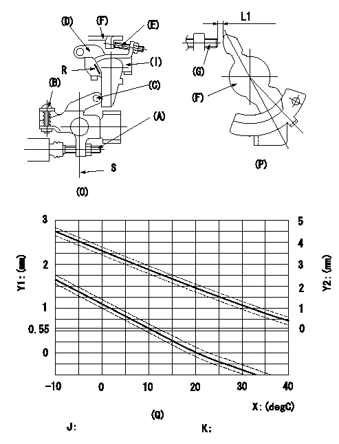
(1)Determine the timer advance angle from the graph in Fig. 3 (Q).
(2)(1) Adjust with the screw (A) so that the timer advance angle determined in the item (1) is obtained.
2. Setting the intermediate lever position (refer to fig 1 and fig 2)
(1)Insert a block gauge L1 between the idling set screw (G) and the control lever (F).
(2)Align the intermediate lever (D) with the aligning line and position it perpendicularly. Adjust the screw (E) so that it contacts the control lever (F) and then tighten the nut.
3. W-CSD lever adjustment [refer to fig 1 (O) and fig 2 (P)]
(1)Insert a block gauge (I) L2 determined from the graph (L-theta) in figure 3 (Q) between the idling set screw (G) and the control lever (F).
(2)Fix screw (B) so that the W-CSD lever (C)'s roller contacts the intermediate lever (D). (Wax temperature at adjustment must not exceed a.)
Adjust the screw (B) until the screw (F) contacts the control lever (G). Then fix locknut (A).
Note:
When inserting the block gauge, separate lever (C) and (D) using screw (B) to prevent excessive force on the lever.
Q = aligning mark
S = intermediate lever perpendicular position
X:Temperature theta (X)
Y1:Timer stroke TA (mm)
Y2:Control lever L dimension (mm; control lever position)
J:Graph TA-X:
-10 <= X (deg C) <= 20: TA = -0.055X + 1.1
20 <= X (deg C) <= 40: TA = -0.0333X + 0.66
K:Graph L-X:
-10 <= X (deg C) <= 20: L = -0.0867X + 3.63
20 <= X (deg C) <= 40: L = -0.075 t + 3.4
----------
L1=1.9+-0.05mm L2=L1+-0.05mm a=30degC
----------
L1=1.9+-0.05mm
----------
L1=1.9+-0.05mm L2=L1+-0.05mm a=30degC
----------
L1=1.9+-0.05mm
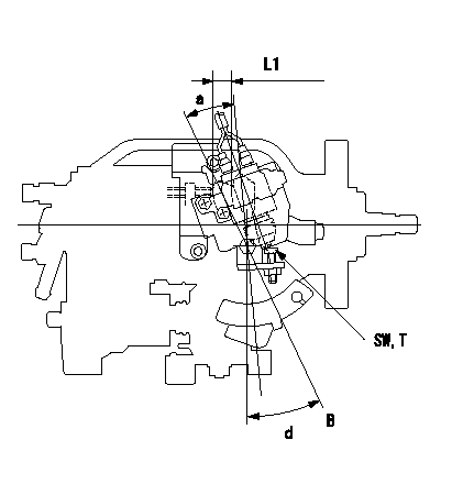
0000001901 ACCELERATOR SWITCH ADJ

Accelerator switch adjustment
ON - OFF changeover point: from idle to a (shim thickness A = L)
Idle~c: ON
c~full: OFF
A = shim thickness
B = idle lever position
----------
a=20+-3deg b=20deg c=20deg L1=12.9mm
----------
a=20+-3deg d=25+-4deg SW=SW10 T=6~9N-m(0.6~0.9kgf-m) L1=12.9mm
----------
a=20+-3deg b=20deg c=20deg L1=12.9mm
----------
a=20+-3deg d=25+-4deg SW=SW10 T=6~9N-m(0.6~0.9kgf-m) L1=12.9mm
Information:
Oil Consumption as an Overhaul Indicator
When an engine's oil consumption has risen to three times the initial (new) consumption rate due to normal wear, then the engine should be scheduled for overhaul. There may be a corresponding increase in blowby and a slight increase in fuel consumption.Overhaul Before Failure
A planned Overhaul Before Failure may be your best value, because you can:* Avoid costly unplanned downtime.* Reuse as many original parts as standards permit.* Extend your engine's service life without the risk of a major catastrophe had you continued to operate to failure.* Get the best cost/value relationship per hour of extended life.After Failure Overhaul
If you experience a major engine failure which requires removal of the engine from the hull, there are also many After Failure Overhaul options available. An overhaul should be performed if your block or crankshaft needs to be repaired.If the block and/or crankshaft is repairable, overhaul cost should be between 40 and 50 percent of the cost of a new engine (with like exchange core).This lower cost can be attributed to Caterpillar "designed-in" features, Caterpillar dealer and Caterpillar Remanufactured exchange components.Overhaul Recommendation
To minimize downtime and provide you with the lowest cost and highest value, Caterpillar recommends that the engine be overhauled before failure by scheduling an overhaul with your Caterpillar dealer. Overhaul programs vary with engine application and from dealer to dealer. Therefore, Caterpillar recommends that you confer with your dealer to obtain specific information regarding the types of programs offered and overhaul services provided for extending the life of your engine.If you elect to perform an overhaul without Caterpillar dealer overhaul service, you should be aware of the maintenance that follows.Inspect/Rebuild or Exchange
Cylinder Head Assembly, Cylinder Packs, Cylinder Liners, Connecting Rods, Pistons, Turbocharger, Oil Pump, Spacer Plates, Fuel Ratio Control, Cam Followers, Fuel Transfer Pump, and Timing Advance.These components should be inspected according to the instructions found in various Caterpillar reusability publications. The Index of Publications on Reusability or Salvage of Used Parts, SEBF8029, lists reusability publications needed for inspecting parts.If the parts comply with established inspection specifications expressed in the reusable parts guideline, the parts should be reused.If the parts are not within specification, the parts should be salvaged, repaired, or replaced. Failure to salvage, repair, or replace out-of-spec parts can result in unscheduled downtime, costly repairs, and damage to other engine parts.In addition, using out-of-spec parts can reduce the engine's efficiency and increase fuel consumption. Reduced engine efficiency and increased fuel consumption translates into higher operating costs. Therefore, Caterpillar recommends salvage, repair, or replacement of out-of-spec parts.Install New
Piston Rings, Valve Rotators, Main Bearings, Rod Bearings, Crankshaft Bearings, and Crankshaft Seals.The thrust, main, and rod bearings, valve rotators, and crankshaft seals will probably not last until the second overhaul. Caterpillar recommends the installation of new parts at each overhaul period.Inspect/Replace
Crankshaft, Camshaft, Camshaft Followers and Bearings, Crankshaft Vibration Damper, Governor, Fuel Pump Camshaft, Fuel Racks, Gear Train Gears and Bushings, and Driven Unit Alignment.The ideal time for inspecting these items is while the engine