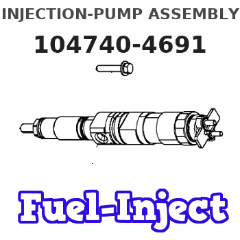
Information injection-pump assembly
ZEXEL
104740-4691
1047404691
Rating:
Cross reference number
ZEXEL
104740-4691
1047404691
Zexel num
Bosch num
Firm num
Name
Calibration Data:
Adjustment conditions
Test oil
1404 Test oil ISO4113orSAEJ967d
1404 Test oil ISO4113orSAEJ967d
Test oil temperature
degC
45
45
50
Nozzle
105000-2010
Bosch type code
NP-DN12SD12TT
Nozzle holder
105780-2080
Opening pressure
MPa
14.7
14.7
15.19
Opening pressure
kgf/cm2
150
150
155
Injection pipe
Inside diameter - outside diameter - length (mm) mm 2-6-840
Inside diameter - outside diameter - length (mm) mm 2-6-840
Transfer pump pressure
kPa
20
20
20
Transfer pump pressure
kgf/cm2
0.2
0.2
0.2
Direction of rotation (viewed from drive side)
Right R
Right R
Injection timing adjustment
Pump speed
r/min
1000
1000
1000
Average injection quantity
mm3/st.
36.1
35.6
36.6
Difference in delivery
mm3/st.
3
Basic
*
Injection timing adjustment_02
Pump speed
r/min
600
600
600
Average injection quantity
mm3/st.
32.3
30.3
34.3
Injection timing adjustment_03
Pump speed
r/min
1000
1000
1000
Average injection quantity
mm3/st.
36.1
35.1
37.1
Injection timing adjustment_04
Pump speed
r/min
2150
2150
2150
Average injection quantity
mm3/st.
33.9
31.9
35.9
Injection timing adjustment_05
Pump speed
r/min
2450
2450
2450
Average injection quantity
mm3/st.
12.1
8.1
16.1
Injection quantity adjustment
Pump speed
r/min
2450
2450
2450
Average injection quantity
mm3/st.
12.1
8.6
15.6
Basic
*
Injection quantity adjustment_02
Pump speed
r/min
2600
2600
2600
Average injection quantity
mm3/st.
5
Governor adjustment
Pump speed
r/min
300
300
300
Average injection quantity
mm3/st.
6.3
4.3
8.3
Difference in delivery
mm3/st.
2
Basic
*
Governor adjustment_02
Pump speed
r/min
300
300
300
Average injection quantity
mm3/st.
6.3
4.3
8.3
Governor adjustment_03
Pump speed
r/min
350
350
350
Average injection quantity
mm3/st.
3
Timer adjustment
Pump speed
r/min
100
100
100
Average injection quantity
mm3/st.
62.5
45
80
Basic
*
Speed control lever angle
Pump speed
r/min
300
300
300
Average injection quantity
mm3/st.
0
0
0
Remarks
Magnet OFF
Magnet OFF
0000000901
Pump speed
r/min
1000
1000
1000
Overflow quantity
cm3/min
378
246
510
Stop lever angle
Pump speed
r/min
1000
1000
1000
Pressure
kPa
411.5
382
441
Pressure
kgf/cm2
4.2
3.9
4.5
Basic
*
Stop lever angle_02
Pump speed
r/min
1000
1000
1000
Pressure
kPa
411.5
382
441
Pressure
kgf/cm2
4.2
3.9
4.5
Stop lever angle_03
Pump speed
r/min
1400
1400
1400
Pressure
kPa
510
481
539
Pressure
kgf/cm2
5.2
4.9
5.5
Stop lever angle_04
Pump speed
r/min
2150
2150
2150
Pressure
kPa
696.5
667
726
Pressure
kgf/cm2
7.1
6.8
7.4
0000001101
Pump speed
r/min
1000
1000
1000
Timer stroke
mm
1.7
1.5
1.9
Basic
*
_02
Pump speed
r/min
1000
1000
1000
Timer stroke
mm
1.7
1.4
2
_03
Pump speed
r/min
1400
1400
1400
Timer stroke
mm
3.2
2.6
3.8
_04
Pump speed
r/min
2150
2150
2150
Timer stroke
mm
6.2
5.6
6.8
0000001201
Max. applied voltage
V
8
8
8
Test voltage
V
13
12
14
Timing setting
K dimension
mm
3.3
3.2
3.4
KF dimension
mm
5.75
5.65
5.85
MS dimension
mm
1.5
1.4
1.6
Control lever angle alpha
deg.
25
21
29
Control lever angle beta
deg.
46
41
51
Information:
Always determine the cause of the engine shutdown. Make necessary repairs before attempting restarting the engine.
Air Shutoff Solenoid (If Equipped)
This optional solenoid is located on top of the engine in the air inlet system. When the solenoid is activated, the solenoid mechanically shuts off inlet air to the engine. The solenoid can only be activated by the overspeed switch or the emergency stop switch. The air shutoff must be reset before the engine can be restarted.Fuel Shutoff Solenoid
This solenoid is located on the governor or on the fuel injection pump. When the solenoid is activated, the solenoid moves the fuel rack (either directly or through the governor) to the FUEL OFF position.Overspeed Shutoffs
Magnetic pickup, (1), mounted in the flywheel housing (2).A magnetic pickup mounted in the flywheel housing senses the passage of the flywheel ring gear teeth. Should the engine speed increase above the overspeed setting of the Electronic Overspeed Switch (118 percent of rated engine speed), the magnetic pickup will sense the overspeed and send a signal to the Electronic Overspeed Switch. The Electronic Overspeed Switch activates both the air (if equipped) and fuel shutoff solenoids.The shutoffs must be reset before the engine will restart. A reset button on the Electronic Overspeed Switch (in the junction box) must be pushed to open the overspeed switch. The air shutoff lever (at the top of the air inlet housing) must be manually reset.Oil Pressure Switches
Typical example of oil pressure switches, mounted in the rear of the junction box.An oil pressure switch has wires connected to the electrical system for alarm or shutoff functions. The oil pressure switch senses oil pressure at the bearing oil gallery. If sufficient oil pressure is not achieved after engine starting, or if the engine has been running normally and then loses oil pressure, the fuel shutoff solenoid is energized to shut the engine off. No resetting procedure is required.Engine Step Oil Pressure
This is an adjustable engine speed setting that protects the engine from a failure caused by too little oil pressure for a specified speed range. This option requires two different oil pressure switches. One switch has a high pressure rating- when the engine is running above the speed setting, the engine must maintain oil pressure higher than the switch rating. The other switch has a low pressure rating- an engine running below the speed setting must maintain oil pressure above the low switch rating.In an automatic start/stop system, an automatic reset switch is used.Water Temperature Contactor Switch
The water temperature contactor switch is located in the cylinder head. High water temperature closes the switch to activate an alarm or fuel shutoff. No resetting is required. The switch opens as the coolant cools.
The sensing element must be submerged in the coolant to operate. Be sure to have an adequate water supply in the jacket water system, or engine damage could result.
Water Level Switch
Typical water level switch, mounted on the side of an expansion tank.If the coolant water level drops below the minimum level, the switch