Information injection-pump assembly
ZEXEL
104740-4640
1047404640
Rating:
Cross reference number
ZEXEL
104740-4640
1047404640
Zexel num
Bosch num
Firm num
Name
Calibration Data:
Adjustment conditions
Test oil
1404 Test oil ISO4113orSAEJ967d
1404 Test oil ISO4113orSAEJ967d
Test oil temperature
degC
45
45
50
Nozzle
105000-2010
Bosch type code
NP-DN12SD12TT
Nozzle holder
105780-2080
Opening pressure
MPa
14.7
14.7
15.19
Opening pressure
kgf/cm2
150
150
155
Injection pipe
Inside diameter - outside diameter - length (mm) mm 2-6-840
Inside diameter - outside diameter - length (mm) mm 2-6-840
Transfer pump pressure
kPa
20
20
20
Transfer pump pressure
kgf/cm2
0.2
0.2
0.2
Direction of rotation (viewed from drive side)
Right R
Right R
Injection timing adjustment
Pump speed
r/min
1000
1000
1000
Average injection quantity
mm3/st.
36.1
35.6
36.6
Difference in delivery
mm3/st.
3
Basic
*
Injection timing adjustment_02
Pump speed
r/min
2450
2450
2450
Average injection quantity
mm3/st.
12.1
8.1
16.1
Injection timing adjustment_03
Pump speed
r/min
2150
2150
2150
Average injection quantity
mm3/st.
33.9
31.9
35.9
Injection timing adjustment_04
Pump speed
r/min
1000
1000
1000
Average injection quantity
mm3/st.
36.1
35.1
37.1
Injection timing adjustment_05
Pump speed
r/min
600
600
600
Average injection quantity
mm3/st.
32.3
30.3
34.3
Injection quantity adjustment
Pump speed
r/min
2450
2450
2450
Average injection quantity
mm3/st.
12.1
8.6
15.6
Basic
*
Injection quantity adjustment_02
Pump speed
r/min
2600
2600
2600
Average injection quantity
mm3/st.
5
Governor adjustment
Pump speed
r/min
300
300
300
Average injection quantity
mm3/st.
6.3
4.3
8.3
Difference in delivery
mm3/st.
2
Basic
*
Governor adjustment_02
Pump speed
r/min
300
300
300
Average injection quantity
mm3/st.
6.3
4.3
8.3
Governor adjustment_03
Pump speed
r/min
350
350
350
Average injection quantity
mm3/st.
3
Timer adjustment
Pump speed
r/min
100
100
100
Average injection quantity
mm3/st.
62.5
45
80
Basic
*
Speed control lever angle
Pump speed
r/min
300
300
300
Average injection quantity
mm3/st.
0
0
0
Remarks
Magnet OFF
Magnet OFF
0000000901
Pump speed
r/min
1000
1000
1000
Overflow quantity
cm3/min
378
246
510
Stop lever angle
Pump speed
r/min
1000
1000
1000
Pressure
kPa
411.5
382
441
Pressure
kgf/cm2
4.2
3.9
4.5
Basic
*
Stop lever angle_02
Pump speed
r/min
1000
1000
1000
Pressure
kPa
411.5
382
441
Pressure
kgf/cm2
4.2
3.9
4.5
Stop lever angle_03
Pump speed
r/min
1400
1400
1400
Pressure
kPa
510
481
539
Pressure
kgf/cm2
5.2
4.9
5.5
Stop lever angle_04
Pump speed
r/min
2150
2150
2150
Pressure
kPa
696.5
667
726
Pressure
kgf/cm2
7.1
6.8
7.4
0000001101
Pump speed
r/min
1000
1000
1000
Timer stroke
mm
1.7
1.5
1.9
Basic
*
_02
Pump speed
r/min
1000
1000
1000
Timer stroke
mm
1.7
1.4
2
_03
Pump speed
r/min
1400
1400
1400
Timer stroke
mm
3.2
2.6
3.8
_04
Pump speed
r/min
2150
2150
2150
Timer stroke
mm
6.2
5.6
6.8
0000001201
Max. applied voltage
V
8
8
8
Test voltage
V
13
12
14
0000001501
Pump speed
r/min
1000
1000
1000
Atmospheric pressure difference
kPa
-21.9
-22.6
-21.2
Atmospheric pressure difference
mmHg
-164
-169
-159
Decrease qty
mm3/st.
5.5
5
6
Basic
*
_02
Pump speed
r/min
1000
1000
1000
Atmospheric pressure difference
kPa
-21.9
-22.6
-21.2
Atmospheric pressure difference
mmHg
-164
-169
-159
Decrease qty
mm3/st.
5.5
4.5
6.5
Timing setting
K dimension
mm
3.3
3.2
3.4
KF dimension
mm
5.75
5.65
5.85
MS dimension
mm
1.2
1.1
1.3
Pre-stroke
mm
0.2
0.18
0.22
Control lever angle alpha
deg.
25
21
29
Control lever angle beta
deg.
46
41
51
Test data Ex:
0000001501 ANEROID COMPENSATOR
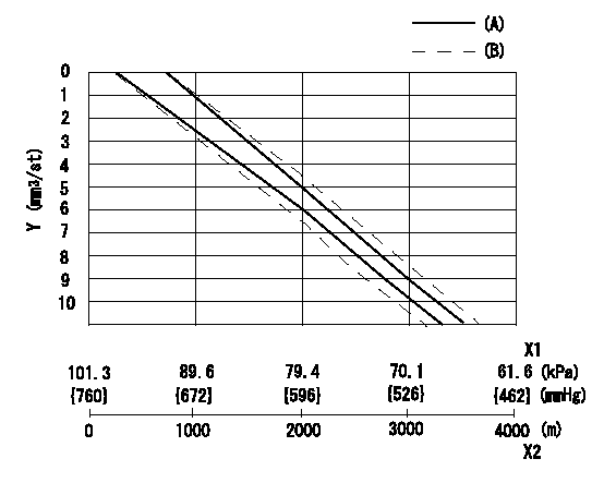
ACS adjustment
Full load injection quantity at high altitudes and ACS adjusting method
1. Full load injection quantity adjustment
(1)Remove the ACS cover and remove the bellows and adjusting shim.
(2)Perform all adjustments as per the adjustment standard except for ACS adjustment.
2. ACS adjustment
Adjust the ACS so that the reduction amount corresponds to the altitude in the table.
X1 = atmospheric pressure
X2 = altitude
Y = decrease quantity
(A) = adjustment value
(B) = test value
----------
N1=1000r/min
----------
----------
N1=1000r/min
----------
Information:
Literature Information
This manual contains information and instructions concerning engine safety, operation, lubrication, and maintenance. Read, study, and keep it available with other literature and engine information.Some photographs or illustrations in this publication show details or attachments that may differ from your engine. Guards and covers may have been removed for illustrative purposes. Continuing improvement and advancement of product design may have caused changes to your engine which are not included in this publication.Whenever a question arises regarding your engine, or this publication, please consult your Caterpillar dealer for the latest available information.Safety
The safety section lists basic safety precautions. In addition, this section identifies hazardous, warning situations. Read and understand the basic precautions listed in the safety section before operating or performing lubrication, maintenance and/or repair on this product.Operation
Engine operation outlined in this publication is basic. Engine operators gain knowledge of the engine through experience, developing operation skills and techniques which enhance efficient and economical engine operation.The operation section is a reference for operators. Photographs and illustrations guide operators through correct procedures of inspecting, starting, operating and stopping the engine. Discussion of gauges and engine control information is included.Maintenance
The maintenance section is a guide to engine care. The illustrated instructions are grouped by maintenance service intervals. The actual operating environment of the engine also governs the maintenance schedule. Under extremely severe, dusty, or frigid operating conditions, lubrication and maintenance checks more frequent than those specified in the Maintenance Schedule may be necessary.Maintenance Intervals
Use the amount of fuel consumed or use the service hour meter to determine service intervals. Calendar intervals shown (daily, weekly, monthly, etc.) can be used, if they provide more convenient servicing schedules and approximate the indicated service hour meter reading. Recommended service should always be performed at the interval that occurs first.We recommend that the maintenance schedules be reproduced for ease of inspection. We also recommend that ongoing maintenance records be kept to document engine service.See the Maintenance Records section of this publication for information regarding documents that are generally accepted as proof of maintenance or repair. Your Caterpillar dealer can assist you in tailoring your Maintenance Schedule to meet the needs of your operating environment.Overhaul
Major engine repair details are not covered in this manual. Major repairs are best left to trained personnel or an authorized Caterpillar dealer.If a major engine failure requiring removal of the engine occurs, numerous after-failure overhaul options available from your Caterpillar dealer. Contact your dealer for information regarding these options.Engine Description
This publication describes the 3408 and 3412 Marine Diesel Engines. These engines are designed primarily for marine propulsion.Engine Storage
For general information, refer to the Engine Lifting & Storage topic. For complete engine storage information refer to Special Instruction SEHS9031, Storage Procedure for Caterpillar Products.California
Proposition 65 Warning
Diesel engine exhaust and some of its constituents are known to the state of California to cause cancer, birth defects, and other reproductive harm.