Information injection-pump assembly
ZEXEL
104740-2940
1047402940

Rating:
Cross reference number
ZEXEL
104740-2940
1047402940
Zexel num
Bosch num
Firm num
Name
104740-2940
INJECTION-PUMP ASSEMBLY
Calibration Data:
Adjustment conditions
Test oil
1404 Test oil ISO4113orSAEJ967d
1404 Test oil ISO4113orSAEJ967d
Test oil temperature
degC
45
45
50
Nozzle
105780-0060
Bosch type code
NP-DN0SD1510
Nozzle holder
105780-2150
Opening pressure
MPa
13
13
13.3
Opening pressure
kgf/cm2
133
133
136
Injection pipe
157805-7320
Injection pipe
Inside diameter - outside diameter - length (mm) mm 2-6-450
Inside diameter - outside diameter - length (mm) mm 2-6-450
Joint assembly
157641-4720
Tube assembly
157641-4020
Transfer pump pressure
kPa
20
20
20
Transfer pump pressure
kgf/cm2
0.2
0.2
0.2
Direction of rotation (viewed from drive side)
Left L
Left L
Injection timing adjustment
Pump speed
r/min
1400
1400
1400
Average injection quantity
mm3/st.
37.2
36.8
37.6
Difference in delivery
mm3/st.
3
Basic
*
Oil temperature
degC
50
48
52
Injection timing adjustment_02
Pump speed
r/min
600
600
600
Average injection quantity
mm3/st.
34
31.5
36.5
Oil temperature
degC
50
48
52
Injection timing adjustment_03
Pump speed
r/min
1000
1000
1000
Average injection quantity
mm3/st.
34.2
31.2
37.2
Oil temperature
degC
50
48
52
Injection timing adjustment_04
Pump speed
r/min
1400
1400
1400
Average injection quantity
mm3/st.
37.2
36.2
38.2
Difference in delivery
mm3/st.
3.5
Basic
*
Oil temperature
degC
50
48
52
Injection timing adjustment_05
Pump speed
r/min
1800
1800
1800
Average injection quantity
mm3/st.
37.4
35.4
39.4
Oil temperature
degC
50
48
52
Injection timing adjustment_06
Pump speed
r/min
2400
2400
2400
Average injection quantity
mm3/st.
37.4
34.4
40.4
Oil temperature
degC
52
50
54
Injection quantity adjustment
Pump speed
r/min
2700
2700
2700
Average injection quantity
mm3/st.
14
12
16
Difference in delivery
mm3/st.
4.5
Basic
*
Oil temperature
degC
55
52
58
Injection quantity adjustment_02
Pump speed
r/min
2700
2700
2700
Average injection quantity
mm3/st.
14
10.5
17.5
Difference in delivery
mm3/st.
5
Basic
*
Oil temperature
degC
55
52
58
Injection quantity adjustment_03
Pump speed
r/min
2800
2800
2800
Average injection quantity
mm3/st.
5
Oil temperature
degC
55
52
58
Governor adjustment
Pump speed
r/min
350
350
350
Average injection quantity
mm3/st.
10.5
9.5
11.5
Difference in delivery
mm3/st.
2
Basic
*
Oil temperature
degC
48
46
50
Governor adjustment_02
Pump speed
r/min
350
350
350
Average injection quantity
mm3/st.
10.5
8.5
12.5
Difference in delivery
mm3/st.
2.5
Basic
*
Oil temperature
degC
48
46
50
Governor adjustment_03
Pump speed
r/min
700
700
700
Average injection quantity
mm3/st.
5
Oil temperature
degC
50
45
55
Boost compensator adjustment
Pump speed
r/min
700
700
700
Average injection quantity
mm3/st.
18
11.5
24.5
Oil temperature
degC
50
48
52
Lever angle (shim thickness)
mm
7.2
7.15
7.25
Boost compensator adjustment_02
Pump speed
r/min
900
900
900
Average injection quantity
mm3/st.
14.2
7.2
21.2
Oil temperature
degC
50
48
52
Lever angle (shim thickness)
mm
7.2
7.15
7.25
Timer adjustment
Pump speed
r/min
100
100
100
Average injection quantity
mm3/st.
60
50
70
Oil temperature
degC
48
46
50
Remarks
Full
Full
Timer adjustment_02
Pump speed
r/min
100
100
100
Average injection quantity
mm3/st.
60
50
70
Oil temperature
degC
48
46
50
Remarks
Full
Full
Speed control lever angle
Pump speed
r/min
350
350
350
Average injection quantity
mm3/st.
0
0
0
Oil temperature
degC
48
46
50
Remarks
Magnet OFF at idling position
Magnet OFF at idling position
0000000901
Pump speed
r/min
1000
1000
1000
Overflow quantity
cm3/min
390
260
520
Oil temperature
degC
50
48
52
Stop lever angle
Pump speed
r/min
1000
1000
1000
Pressure
kPa
412
373
451
Pressure
kgf/cm2
4.2
3.9
4.5
Basic
*
Oil temperature
degC
50
48
52
Stop lever angle_02
Pump speed
r/min
1000
1000
1000
Pressure
kPa
412
373
451
Pressure
kgf/cm2
4.2
3.8
4.6
Basic
*
Oil temperature
degC
50
48
52
Stop lever angle_03
Pump speed
r/min
1800
1800
1800
Pressure
kPa
588
549
627
Pressure
kgf/cm2
6
5.6
6.4
Oil temperature
degC
50
48
52
Stop lever angle_04
Pump speed
r/min
2400
2400
2400
Pressure
kPa
736
687
785
Pressure
kgf/cm2
7.5
7
8
Oil temperature
degC
52
50
54
0000001101
Pump speed
r/min
1000
1000
1000
Timer stroke
mm
3.1
2.9
3.3
Basic
*
Oil temperature
degC
50
48
52
_02
Pump speed
r/min
1000
1000
1000
Timer stroke
mm
3.1
2.8
3.4
Basic
*
Oil temperature
degC
50
48
52
_03
Pump speed
r/min
1800
1800
1800
Timer stroke
mm
6.8
6.3
7.3
Oil temperature
degC
50
48
52
_04
Pump speed
r/min
2400
2400
2400
Timer stroke
mm
8.6
8.1
9
Oil temperature
degC
52
50
54
0000001201
Max. applied voltage
V
8
8
8
Test voltage
V
13
12
14
Timing setting
K dimension
mm
3.3
3.2
3.4
KF dimension
mm
6.78
6.68
6.88
MS dimension
mm
0.8
0.7
0.9
Control lever angle alpha
deg.
25
23
27
Control lever angle beta
deg.
44
39
49
Test data Ex:
0000001801 W-CSD ADJUSTMENT
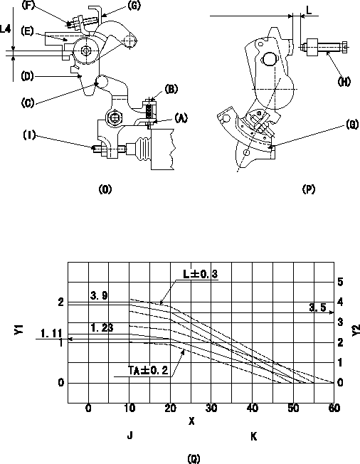
Adjustment of the W-CSD
1. Adjustment of the advance angle of the timer
(1)Determine the timer advance angle from the graph in Fig. 3 (Q).
(2)(1) Adjust using the screw (I) so that the timer advance angle determined in item (1) is obtained.
2. Setting the intermediate lever position (refer to fig 1 and fig 2)
(1)Insert a block gauge L1 between the idling set screw (H) and the control lever (G).
(2)Insert a shim of thickness L2 mm between the intermediate lever (D) and the intermediate lever bracket (E). Ensure the screw (F) contacts the control lever (G), then fix the nut.
3. W-CSD lever adjustment [refer to fig 1 (O) and fig 2 (P)]
(1)After completing 2. above, remove the block gauge L3 and the shim L4.
(2)Insert a block gauge L5 determined from the graph (L-theta) in figure 3 (Q) between the idling set screw (H) and the control lever (G).
(3)Adjust the screw (B) until the screw (F) contacts the control lever (G). Then fix locknut (A).
Note:
The temperature of the wax at adjustment must not exceed a.
X:Temperature X (deg C)
Y1:Timer stroke TA (mm)
Y2:Control lever L dimension (mm; control lever position)
J:Graph TA-X:
X (deg C) <= 10: TA = 1.23
10 <= X (deg C) <= 20:TA = -0.012X + 1.35
20<= X (deg C) <= 53.6: TA =-0.0330X + 1.77
K:Graph L-X:
X (deg C) <= 10: L = 3.9
10 <= X (deg C) <= 20: L = -0.04X + 4.3
20 <= X (deg C) <= 52.3 : L =-0.108X + 5.66
----------
L1=L=3.5+-0.05mm L2=5.3+-0.05mm L3=3.5mm L4=5.3mm L5=L+-0.05mm a=30degC
----------
L=3.5+-0.05mm L4=5.3mm
----------
L1=L=3.5+-0.05mm L2=5.3+-0.05mm L3=3.5mm L4=5.3mm L5=L+-0.05mm a=30degC
----------
L=3.5+-0.05mm L4=5.3mm
0000001901 DASHPOT ADJUSTMENT
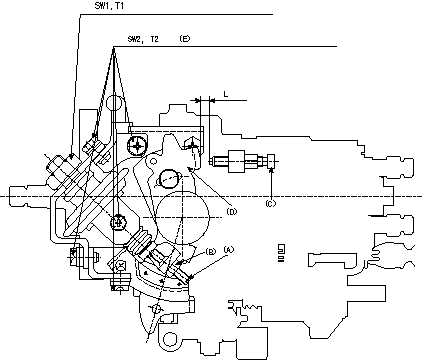
Adjustment of the dash pot
1. Insert a block gauge L (thickness gauge) between the idle set screw (C) and the control lever (D).
2. In the above condition, adjust the position of the dash pot so that the dash pot adjustment screw (A) contacts the push rod and then fix the screw using the nut (B).
T3T3
Note:
(1)The adjusting screw and pushrod contact faces must be smooth.
(2)Confirm that the control lever returns to the idling position.
(E): 6 locations
----------
T3=5~7Nm{0.5~0.7kgfm} L=6.0+-0.05mm
----------
T1=15.0~20.0Nm{1.5~2.0kgfm} T2=6.0~0.9Nm{0.6~0.9kgfm} SW1=SW22mm SW2=SW10mm L=6.0+-0.05mm
----------
T3=5~7Nm{0.5~0.7kgfm} L=6.0+-0.05mm
----------
T1=15.0~20.0Nm{1.5~2.0kgfm} T2=6.0~0.9Nm{0.6~0.9kgfm} SW1=SW22mm SW2=SW10mm L=6.0+-0.05mm
Information:
Belts, Hoses and Clamps
Inspect/Replace Accessory Drive Belts
Inspect the condition and adjustment of alternator drive belts. Examine belts for wear and replace if any signs of wear are present. Loose or worn pulley grooves cause belt slippage and low accessory drive speed.If belts are too loose, they vibrate enough to cause unnecessary wear on the belts and pulleys and possibly slip enough to cause overheating. If belts are too tight, unnecessary stresses are placed upon the pulley bearings and belts which can shorten the life of both.If one belt in a set requires replacement, always install a new matched set of belts. Never replace just the worn belt. If only the worn belt is replaced, the new belt will carry all the load, as it will not be stretched as much as the older belts. All the belts will fail in rapid succession.Adjust
1. Remove belt guard. Inspect the condition and adjustment of alternator belts and accessory drive belts, if equipped.2. To check the belt tension, apply 110 Newton (25 lb) force, perpendicular to the belt, midway between the driving and driven pulley. Measure the belt deflection. Correctly adjusted belts will deflect 13 to 20 mm (1/2 to 7/8 inch). Adjust the belt tension as required.If belt does not require replacement or adjustment, install the belt guard. If belt requires adjustment or replacement, do not install the belt guard.3. Loosen the mounting pivot bolt (1). Loosen the adjustment nut(s) (2).4. Adjust the alternator in or out by either tightening or loosening adjustment nut(s) as required to obtain the correct adjustment.5. Tighten bolts (1) and (2). Check the belt tension. Install the belt guard.If new belts are installed, check belt adjustment again after 30 minutes of engine operation. Repeat belt tightening if required.Adjust Accessory Drive Belts
If engine is equipped with any other belt driven equipment, check and adjust them as required.Inspect/Replace Hoses and Clamps
Hose replacement prior to failure is a good preventive maintenance practice. Replacing a hose before it fails reduces the chances for unscheduled downtime. By replacing a hose that is cracked, soft or leaking, major repairs will be avoided that could result in a severe engine overheating problem.* Inspect all hoses for leaks due to cracking, softness and loose clamps.* Replace hoses that are cracked or soft and tighten loose clamps. See the Torque for Standard Hose Clamps chart in the Torque Specifications section of this publication for the appropriate torque. For constant torque hose clamps, see the Torque Specifications section in this publication.Engine Valve Lash
Check/Adjust
To prevent possible injury, do not use the starting motor to turn the flywheel. Be sure the starting motors are disabled and engine cannot be started while this maintenance is being performed.Hot engine components can cause burns. Allow additional time for the engine to cool before measuring valve lash.
Measure the valve lash with the engine stopped. To obtain an accurate measurement, allow at least 20 minutes for the valves to cool to engine cylinder head and block temperature.
Initial valve lash adjustment (At First Oil
Have questions with 104740-2940?
Group cross 104740-2940 ZEXEL
Nissan
Nissan
Nissan
104740-2940
INJECTION-PUMP ASSEMBLY