Information injection-pump assembly
ZEXEL
104740-2380
1047402380
Rating:
Cross reference number
ZEXEL
104740-2380
1047402380
Zexel num
Bosch num
Firm num
Name
104740-2380
INJECTION-PUMP ASSEMBLY
Calibration Data:
Adjustment conditions
Test oil
1404 Test oil ISO4113orSAEJ967d
1404 Test oil ISO4113orSAEJ967d
Test oil temperature
degC
45
45
50
Nozzle
105780-0060
Bosch type code
NP-DN0SD1510
Nozzle holder
105780-2150
Opening pressure
MPa
13
13
13.3
Opening pressure
kgf/cm2
133
133
136
Injection pipe
157805-7320
Injection pipe
Inside diameter - outside diameter - length (mm) mm 2-6-450
Inside diameter - outside diameter - length (mm) mm 2-6-450
Joint assembly
157641-4720
Tube assembly
157641-4020
Transfer pump pressure
kPa
20
20
20
Transfer pump pressure
kgf/cm2
0.2
0.2
0.2
Direction of rotation (viewed from drive side)
Left L
Left L
Injection timing adjustment
Pump speed
r/min
1400
1400
1400
Average injection quantity
mm3/st.
37.2
36.8
37.6
Difference in delivery
mm3/st.
3
Basic
*
Oil temperature
degC
50
48
52
Injection timing adjustment_02
Pump speed
r/min
600
600
600
Average injection quantity
mm3/st.
33
30.5
35.5
Oil temperature
degC
50
48
52
Injection timing adjustment_03
Pump speed
r/min
1000
1000
1000
Average injection quantity
mm3/st.
33.8
31.3
36.3
Oil temperature
degC
50
48
52
Injection timing adjustment_04
Pump speed
r/min
1400
1400
1400
Average injection quantity
mm3/st.
37.2
36.2
38.2
Difference in delivery
mm3/st.
3.5
Basic
*
Oil temperature
degC
50
48
52
Injection timing adjustment_05
Pump speed
r/min
1800
1800
1800
Average injection quantity
mm3/st.
37.3
35.3
39.3
Oil temperature
degC
50
48
52
Injection timing adjustment_06
Pump speed
r/min
2400
2400
2400
Average injection quantity
mm3/st.
37.2
34.7
39.7
Oil temperature
degC
52
50
54
Injection quantity adjustment
Pump speed
r/min
2700
2700
2700
Average injection quantity
mm3/st.
14
12
16
Difference in delivery
mm3/st.
4.5
Basic
*
Oil temperature
degC
55
52
58
Injection quantity adjustment_02
Pump speed
r/min
2800
2800
2800
Average injection quantity
mm3/st.
5
Oil temperature
degC
55
52
58
Governor adjustment
Pump speed
r/min
350
350
350
Average injection quantity
mm3/st.
10.5
9.5
11.5
Difference in delivery
mm3/st.
2
Basic
*
Oil temperature
degC
48
46
50
Governor adjustment_02
Pump speed
r/min
700
700
700
Average injection quantity
mm3/st.
5
Oil temperature
degC
48
46
50
Boost compensator adjustment
Pump speed
r/min
700
700
700
Average injection quantity
mm3/st.
16
9.5
22.5
Oil temperature
degC
50
48
52
Lever angle (shim thickness)
mm
7.2
7.2
7.2
Remarks
From idle
From idle
Boost compensator adjustment_02
Pump speed
r/min
900
900
900
Average injection quantity
mm3/st.
11.6
4.6
18.6
Oil temperature
degC
50
48
52
Lever angle (shim thickness)
mm
7.2
7.2
7.2
Remarks
From idle
From idle
Timer adjustment
Pump speed
r/min
100
100
100
Average injection quantity
mm3/st.
60
50
70
Basic
*
Oil temperature
degC
48
46
50
Remarks
Full
Full
Speed control lever angle
Pump speed
r/min
350
350
350
Average injection quantity
mm3/st.
0
0
0
Oil temperature
degC
48
46
50
Remarks
Magnet OFF at idling position
Magnet OFF at idling position
0000000901
Pump speed
r/min
1000
1000
1000
Overflow quantity with S/T ON
cm3/min
440
310
570
Oil temperature
degC
50
48
52
Stop lever angle
Pump speed
r/min
1000
1000
1000
Pressure with S/T ON
kPa
422
393
451
Pressure with S/T ON
kgf/cm2
4.3
4
4.6
Pressure with S/T OFF
kPa
353
304
402
Pressure with S/T OFF
kgf/cm2
3.6
3.1
4.1
Basic
*
Oil temperature
degC
50
48
52
Remarks
ON
ON
Stop lever angle_02
Pump speed
r/min
1000
1000
1000
Pressure
kPa
421.5
382
461
Pressure
kgf/cm2
4.3
3.9
4.7
Basic
*
Oil temperature
degC
50
48
52
Stop lever angle_03
Pump speed
r/min
1800
1800
1800
Pressure
kPa
588.5
549
628
Pressure
kgf/cm2
6
5.6
6.4
Oil temperature
degC
50
48
52
Stop lever angle_04
Pump speed
r/min
2400
2400
2400
Pressure
kPa
726
677
775
Pressure
kgf/cm2
7.4
6.9
7.9
Oil temperature
degC
52
50
54
0000001101
Pump speed
r/min
1000
1000
1000
Timer stroke with S/T ON
mm
2.7
2.5
2.9
Timer stroke with S/T OFF
mm
1.3
0.9
1.7
Basic
*
Oil temperature
degC
50
48
52
Remarks
ON
ON
_02
Pump speed
r/min
1000
1000
1000
Timer stroke with S/T ON
mm
2.7
2.4
3
Timer stroke with S/T OFF
mm
1.3
0.8
1.8
Basic
*
Oil temperature
degC
50
48
52
_03
Pump speed
r/min
1800
1800
1800
Timer stroke with S/T ON
mm
6.4
5.9
6.9
Oil temperature
degC
50
48
52
_04
Pump speed
r/min
2400
2400
2400
Timer stroke with S/T ON
mm
8.55
8.1
9
Oil temperature
degC
52
50
54
0000001201
Max. applied voltage
V
8
8
8
Test voltage
V
13
12
14
Timing setting
K dimension
mm
3.3
3.2
3.4
KF dimension
mm
6.78
6.68
6.88
MS dimension
mm
0.8
0.7
0.9
Control lever angle alpha
deg.
25
23
27
Control lever angle beta
deg.
44
39
49
Test data Ex:
0000001801 POTENTIOMETER ADJUSTMENT
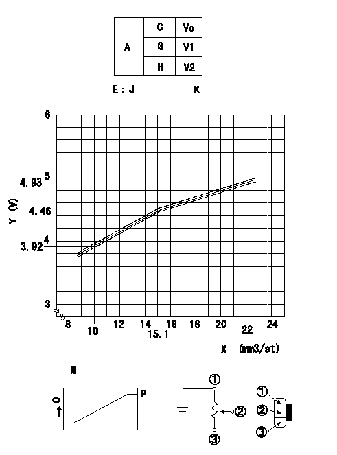
Adjustment of the potentiometer
At pump speed N and with the control lever angle at a from the idle position (clearance L), convert the injection quantity obtained to a voltage value using the graph and adjust the potentiometer.
Vo:Output voltage
Q:Injection quantity
A:Performance standards
C:Position of the control lever
G:Idle
H:Full speed
E:J = formula V+-0.03 = 0.1065Q+2.8519 (Q < 15.2 mm3/st)
V+-0.03 = 0.0674Q + 3.4462 (Q>=15.2 (mm3/st)
K = Vi: applied voltage
X:Injection quantity (mm3/st)
Y:Voltage (V)
M:Connecting diagram for the potentiometer
O:Output
P:Output when (2) and (3) connected.
----------
N=700(r/min) a=11(deg) L=7.2(mm) Vi=10(V)
----------
V1=0.5++(V) V2=-(V)
----------
N=700(r/min) a=11(deg) L=7.2(mm) Vi=10(V)
----------
V1=0.5++(V) V2=-(V)
0000001901 W-CSD ADJUSTMENT
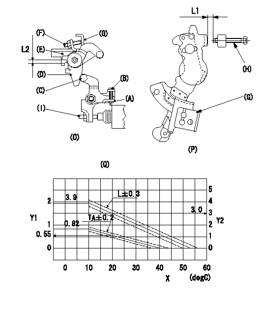
Adjustment of the W-CSD
1. Adjustment of the advance angle of the timer
(1)Determine the timer advance angle from the figure (Q)'s graph.
(2)(1) Adjust using the screw (I) so that the timer advance angle determined in item (1) is obtained.
2. Intermediate lever position setting [refer to fig (O), (P)]
(1)Insert a block gauge L1 between the idling set screw (H) and the control lever (G).
(2)Insert a shim thickness L2+-0.05 mm between the intermediate lever (D) and the intermediate lever bracket (E). Hold control lever (G) against screw (F) then fix the nut.
3. W-CSD lever adjustment [refer to fig (O) and fig (P)]
(1)Insert a block gauge thickness L3 determined from the graph Q (L-theta) between the idling set screw (H) and the control lever (G).
(2)Adjust the screw (B) until the screw (F) contacts the control lever (G). Then fix locknut (A).
Note
The temperature of the wax at adjustment must not exceed a.
X:Temperature theta (deg C)
Y1:Timer stroke TA (mm)
Y2:Control lever L dimension (mm; control lever position)
Graph TA-theta
theta (deg C) <= 10: TA = 0.82
10 <= theta (deg C) <= 20: TA = -0.027 theta + 1.09
20 <= theta (deg C) <= 40: TA = -0.0275 theta + 1.1
L-theta graph
theta (deg C) <= 10: L = 3.9
10 <= theta (deg C) <= 30 L = -0.09 theta + 4.8
30 <= theta (deg C) <= 54.3 L = -0.086 theta + 4.68
----------
L1=3.0+-0.05(mm) L2=5.3(mm) L3=L+-0.5(mm) a=30(degC)
----------
L1=3.0+-0.05(mm) L2=5.3(mm)
----------
L1=3.0+-0.05(mm) L2=5.3(mm) L3=L+-0.5(mm) a=30(degC)
----------
L1=3.0+-0.05(mm) L2=5.3(mm)
0000002001 DASHPOT ADJUSTMENT
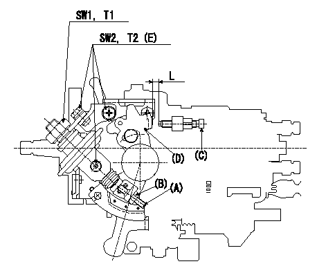
Adjustment of the dash pot
1. Insert a block gauge L (thickness gauge) between the idle set screw (C) and the control lever (D).
2. In the above condition, adjust so that the dashpot adjusting screw (A) contacts the pushrod. Then, fix using the locknut (B) (Tightening torque T3).
3. Confirm that the control lever returns to the idling position without the adjusting screw or dashpot sticking or coming loose.
(E) 3 locations
----------
T3=4.9~6.9(N-m)(0.5~0.7(kgf-m)) L=6.0+-0.05(mm)
----------
T1=14.7~19.6(N-m)(1.5~2.0(kgf-m)) T2=5.9~8.8(N-m)(0.6~0.9(kgf-m)) SW1=22(mm) SW2=10(mm) L=6.0+-0.05(mm)
----------
T3=4.9~6.9(N-m)(0.5~0.7(kgf-m)) L=6.0+-0.05(mm)
----------
T1=14.7~19.6(N-m)(1.5~2.0(kgf-m)) T2=5.9~8.8(N-m)(0.6~0.9(kgf-m)) SW1=22(mm) SW2=10(mm) L=6.0+-0.05(mm)
Information:
Start By:a. remove oil pumpb. remove oil pan plate
Keep all parts clean from contaminants. Contaminants put into the system may cause rapid wear and shortened component life.
1. Remove No. 1, 3, 5 and 7 main bearing caps (1). Remove the lower halves of the main bearings from the main bearing caps.
If the crankshaft is turned in the wrong direction, the tab on the bearing will be pushed between the crankshaft and the bearing area in the cylinder block. This can result in damage to the cylinder block and/or the crankshaft.
2. Install tool (A) in the hole in the crankshaft journal, and turn the crankshaft to remove the upper halves of main bearings (2).3. Remove crankshaft thrust bearings (3). Install the main bearings dry when the clearance checks are made. Put clean engine oil on the main bearings for final assembly.
Make sure the upper and lower halves of the main bearings are installed so the bearing tabs fit into the notch in the cylinder block and the main bearing caps.
4. Use tool (A), and install new upper halves of main bearings (2) in the cylinder block. Install new lower halves of main bearings (2) in main bearing caps (1).
When the bearing clearance is checked and the engine is in an upright position (vertical position with cylinder head on top), the crankshaft will have to be lifted up and held against the upper halves of the main bearings to get a correct measurement with the Plastigage. The Plastigage will not hold the weight of the crankshaft and give a correct indication. If the engine is in a horizontal position, it is not necessary to hold the crankshaft up. Do not turn the crankshaft when the Plastigage is in position to check clearances.
For complete details concerning measuring bearing clearances, see Engine Bearings And Crankshafts, Form No. SEBD0531.5. Check the main bearing clearance with Plastigage (B) as follows:a. Put a piece of Plastigage (B) on the crankshaft journals as shown.
Make sure the part number on the main bearing cap is toward the front of the engine and the number on the main bearing cap is the same as the number on the cylinder block on the left side of each main bearing cap.
b. Put main bearing caps (1) in position in the engine. Put 2P2506 Thread Lubricant on the bolt threads and the face of the washers, and install the bolts. Tighten the bolts to a torque of 40 4 N m (30 3 lb ft).c. Put a mark on each bolt and main bearing cap; then tighten the bolts 90° more.d. Remove the main bearing caps, and measure the Plastigage to find the bearing clearance. The main bearing clearance for new bearings must be 0.076 to 0.165 mm (.0030 to .0065 in). Maximum permissible clearance with used bearings is 0.25 mm (.010 in). 6. Put clean oil on the thrust bearing, and install a new thrust bearing for the rear main bearing. Install the thrust bearing with the identification
Have questions with 104740-2380?
Group cross 104740-2380 ZEXEL
104740-2380
INJECTION-PUMP ASSEMBLY