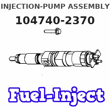
Information injection-pump assembly
ZEXEL
104740-2370
1047402370
Rating:
Cross reference number
ZEXEL
104740-2370
1047402370
Zexel num
Bosch num
Firm num
Name
104740-2370
INJECTION-PUMP ASSEMBLY
Calibration Data:
Adjustment conditions
Test oil
1404 Test oil ISO4113orSAEJ967d
1404 Test oil ISO4113orSAEJ967d
Test oil temperature
degC
45
45
50
Nozzle
105780-0060
Bosch type code
NP-DN0SD1510
Nozzle holder
105780-2150
Opening pressure
MPa
13
13
13.3
Opening pressure
kgf/cm2
133
133
136
Injection pipe
157805-7320
Injection pipe
Inside diameter - outside diameter - length (mm) mm 2-6-450
Inside diameter - outside diameter - length (mm) mm 2-6-450
Joint assembly
157641-4720
Tube assembly
157641-4020
Transfer pump pressure
kPa
20
20
20
Transfer pump pressure
kgf/cm2
0.2
0.2
0.2
Direction of rotation (viewed from drive side)
Left L
Left L
Injection timing adjustment
Pump speed
r/min
800
800
800
Boost pressure
kPa
0
0
0
Boost pressure
mmHg
0
0
0
Average injection quantity
mm3/st.
32
31.6
32.4
Difference in delivery
mm3/st.
2.5
Basic
*
Oil temperature
degC
50
48
52
Remarks
Full
Full
Injection timing adjustment_02
Pump speed
r/min
900
900
900
Boost pressure
kPa
43.3
42
44.6
Boost pressure
mmHg
325
315
335
Average injection quantity
mm3/st.
45.1
44.7
45.5
Difference in delivery
mm3/st.
2.5
Basic
*
Oil temperature
degC
50
48
52
Remarks
CBS
CBS
Injection timing adjustment_03
Pump speed
r/min
500
500
500
Boost pressure
kPa
0
0
0
Boost pressure
mmHg
0
0
0
Average injection quantity
mm3/st.
40.9
36.4
45.4
Oil temperature
degC
48
46
50
Injection timing adjustment_04
Pump speed
r/min
600
600
600
Boost pressure
kPa
0
0
0
Boost pressure
mmHg
0
0
0
Average injection quantity
mm3/st.
35.7
33.7
37.7
Oil temperature
degC
50
48
52
Injection timing adjustment_05
Pump speed
r/min
800
800
800
Boost pressure
kPa
0
0
0
Boost pressure
mmHg
0
0
0
Average injection quantity
mm3/st.
32
31
33
Basic
*
Oil temperature
degC
50
48
52
Remarks
Full
Full
Injection timing adjustment_06
Pump speed
r/min
900
900
900
Boost pressure
kPa
43.3
42
44.6
Boost pressure
mmHg
325
315
335
Average injection quantity
mm3/st.
45.1
44.1
46.1
Difference in delivery
mm3/st.
3
Basic
*
Oil temperature
degC
50
48
52
Remarks
CBS
CBS
Injection timing adjustment_07
Pump speed
r/min
1400
1400
1400
Boost pressure
kPa
66.7
65.4
68
Boost pressure
mmHg
500
490
510
Average injection quantity
mm3/st.
51.6
49.6
53.6
Oil temperature
degC
50
48
52
Injection timing adjustment_08
Pump speed
r/min
1800
1800
1800
Boost pressure
kPa
66.7
65.4
68
Boost pressure
mmHg
500
490
510
Average injection quantity
mm3/st.
51.7
49.7
53.7
Oil temperature
degC
50
48
52
Injection timing adjustment_09
Pump speed
r/min
2200
2200
2200
Boost pressure
kPa
66.7
65.4
68
Boost pressure
mmHg
500
490
510
Average injection quantity
mm3/st.
48.3
45.3
51.3
Oil temperature
degC
52
50
54
Injection timing adjustment_10
Pump speed
r/min
2400
2400
2400
Boost pressure
kPa
66.7
65.4
68
Boost pressure
mmHg
500
490
510
Average injection quantity
mm3/st.
46.2
42.7
49.7
Oil temperature
degC
52
50
54
Injection quantity adjustment
Pump speed
r/min
2700
2700
2700
Boost pressure
kPa
66.7
65.4
68
Boost pressure
mmHg
500
490
510
Average injection quantity
mm3/st.
19.5
17.5
21.5
Difference in delivery
mm3/st.
5
Basic
*
Oil temperature
degC
55
52
58
Injection quantity adjustment_02
Pump speed
r/min
2700
2700
2700
Boost pressure
kPa
66.7
65.4
68
Boost pressure
mmHg
500
490
510
Average injection quantity
mm3/st.
19.5
16
23
Difference in delivery
mm3/st.
5.5
Basic
*
Oil temperature
degC
55
52
58
Injection quantity adjustment_03
Pump speed
r/min
2950
2950
2950
Boost pressure
kPa
66.7
65.4
68
Boost pressure
mmHg
500
490
510
Average injection quantity
mm3/st.
6
Oil temperature
degC
55
52
58
Governor adjustment
Pump speed
r/min
400
400
400
Boost pressure
kPa
0
0
0
Boost pressure
mmHg
0
0
0
Average injection quantity
mm3/st.
10.5
9.5
11.5
Difference in delivery
mm3/st.
2
Basic
*
Oil temperature
degC
48
46
50
Governor adjustment_02
Pump speed
r/min
400
400
400
Boost pressure
kPa
0
0
0
Boost pressure
mmHg
0
0
0
Average injection quantity
mm3/st.
10.5
8.5
12.5
Difference in delivery
mm3/st.
2.5
Basic
*
Oil temperature
degC
48
46
50
Governor adjustment_03
Pump speed
r/min
800
800
800
Boost pressure
kPa
0
0
0
Boost pressure
mmHg
0
0
0
Average injection quantity
mm3/st.
3
Oil temperature
degC
50
48
52
Boost compensator adjustment
Pump speed
r/min
700
700
700
Boost pressure
kPa
0
0
0
Boost pressure
mmHg
0
0
0
Average injection quantity
mm3/st.
15.9
9.4
22.4
Oil temperature
degC
50
48
52
Lever angle (shim thickness)
mm
5.8
5.8
5.8
Remarks
From idle
From idle
Boost compensator adjustment_02
Pump speed
r/min
900
900
900
Boost pressure
kPa
0
0
0
Boost pressure
mmHg
0
0
0
Average injection quantity
mm3/st.
11.3
4.3
18.3
Oil temperature
degC
50
48
52
Lever angle (shim thickness)
mm
5.8
5.8
5.8
Remarks
From idle
From idle
Timer adjustment
Pump speed
r/min
100
100
100
Boost pressure
kPa
0
0
0
Boost pressure
mmHg
0
0
0
Average injection quantity
mm3/st.
67
62
72
Basic
*
Oil temperature
degC
48
46
50
Remarks
IDLE
IDLE
Timer adjustment_02
Pump speed
r/min
100
100
100
Boost pressure
kPa
0
0
0
Boost pressure
mmHg
0
0
0
Average injection quantity
mm3/st.
67
62
72
Basic
*
Oil temperature
degC
48
46
50
Remarks
Full
Full
Timer adjustment_03
Pump speed
r/min
100
100
100
Boost pressure
kPa
0
0
0
Boost pressure
mmHg
0
0
0
Average injection quantity
mm3/st.
67
62
72
Oil temperature
degC
48
46
50
Speed control lever angle
Pump speed
r/min
400
400
400
Boost pressure
kPa
0
0
0
Boost pressure
mmHg
0
0
0
Average injection quantity
mm3/st.
0
0
0
Oil temperature
degC
48
46
50
Remarks
Magnet OFF at idling position
Magnet OFF at idling position
0000000901
Pump speed
r/min
900
900
900
Boost pressure
kPa
66.7
65.4
68
Boost pressure
mmHg
500
490
510
Overflow quantity
cm3/min
380
250
510
Oil temperature
degC
50
48
52
Stop lever angle
Pump speed
r/min
900
900
900
Boost pressure
kPa
66.7
65.4
68
Boost pressure
mmHg
500
490
510
Pressure
kPa
382
353
411
Pressure
kgf/cm2
3.9
3.6
4.2
Basic
*
Oil temperature
degC
50
48
52
Stop lever angle_02
Pump speed
r/min
600
600
600
Boost pressure
kPa
66.7
65.4
68
Boost pressure
mmHg
500
490
510
Pressure
kPa
323.5
284
363
Pressure
kgf/cm2
3.3
2.9
3.7
Oil temperature
degC
50
48
52
Stop lever angle_03
Pump speed
r/min
900
900
900
Boost pressure
kPa
66.7
65.4
68
Boost pressure
mmHg
500
490
510
Pressure
kPa
382.5
343
422
Pressure
kgf/cm2
3.9
3.5
4.3
Basic
*
Oil temperature
degC
50
48
52
Stop lever angle_04
Pump speed
r/min
1400
1400
1400
Boost pressure
kPa
66.7
65.4
68
Boost pressure
mmHg
500
490
510
Pressure
kPa
490.5
451
530
Pressure
kgf/cm2
5
4.6
5.4
Oil temperature
degC
50
48
52
Stop lever angle_05
Pump speed
r/min
2200
2200
2200
Boost pressure
kPa
66.7
65.4
68
Boost pressure
mmHg
500
490
510
Pressure
kPa
657
608
706
Pressure
kgf/cm2
6.7
6.2
7.2
Oil temperature
degC
52
50
54
0000001101
Pump speed
r/min
900
900
900
Boost pressure
kPa
66.7
65.4
68
Boost pressure
mmHg
500
490
510
Timer stroke
mm
3
2.8
3.2
Basic
*
Oil temperature
degC
50
48
52
_02
Pump speed
r/min
600
600
600
Boost pressure
kPa
66.7
65.4
68
Boost pressure
mmHg
500
490
510
Timer stroke
mm
1
0.4
1.6
Oil temperature
degC
50
48
52
_03
Pump speed
r/min
900
900
900
Boost pressure
kPa
66.7
65.4
68
Boost pressure
mmHg
500
490
510
Timer stroke
mm
3
2.7
3.3
Basic
*
Oil temperature
degC
50
48
52
_04
Pump speed
r/min
1400
1400
1400
Boost pressure
kPa
66.7
65.4
68
Boost pressure
mmHg
500
490
510
Timer stroke
mm
5.9
5.5
6.3
Oil temperature
degC
50
48
52
_05
Pump speed
r/min
1800
1800
1800
Boost pressure
kPa
66.7
65.4
68
Boost pressure
mmHg
500
490
510
Timer stroke
mm
8.2
7.7
8.7
Oil temperature
degC
50
48
52
_06
Pump speed
r/min
2200
2200
2200
Boost pressure
kPa
66.7
65.4
68
Boost pressure
mmHg
500
490
510
Timer stroke
mm
8.95
8.5
9.4
Oil temperature
degC
52
50
54
0000001201
Max. applied voltage
V
8
8
8
Test voltage
V
13
12
14
0000001401
Pump speed
r/min
900
900
900
Boost pressure
kPa
0
0
0
Boost pressure
mmHg
0
0
0
Average injection quantity
mm3/st.
23.5
22.5
24.5
Timer stroke TA
mm
2.7
2.7
2.7
Timer stroke variation dT
mm
0.3
0.1
0.5
Basic
*
Oil temperature
degC
50
48
52
_02
Pump speed
r/min
900
900
900
Boost pressure
kPa
0
0
0
Boost pressure
mmHg
0
0
0
Average injection quantity
mm3/st.
23.5
22
25
Timer stroke TA
mm
2.7
2.3
3.1
Oil temperature
degC
50
48
52
Timing setting
K dimension
mm
3.3
3.2
3.4
KF dimension
mm
6.29
6.19
6.39
MS dimension
mm
0.9
0.8
1
BCS stroke
mm
4.6
4.4
4.8
Control lever angle alpha
deg.
25
23
27
Control lever angle beta
deg.
42
37
47
Test data Ex:
0000001801 POTENTIOMETER ADJUSTMENT
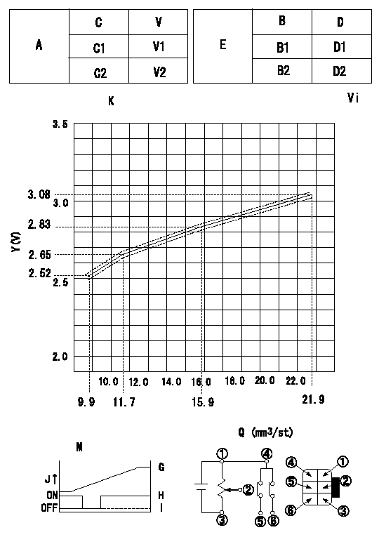
Adjustment of the potentiometer
At pump speed N and with the control lever angle at a from the idle position (clearance L), convert the injection quantity obtained to a voltage value using the graph and adjust the potentiometer.
V:Output voltage
Q:Injection quantity
A:Performance standards
C:Position of the control lever
C1:Idle
C2:Full speed
E:Standards for the potentiometer's ON - OFF switch
B:Conversion point
B1:OFF-->ON
B2:OFF-->ON
D:Lever opening (from idle)
K = formula V+-0.03 = 0.071693Q+1.81172 Q <= 11.7 (mm3/st)
V+-0.03 = 0.0416286Q + 2.16366 Q>11.7 (mm3/st)
Vi:Applied voltage
X:Injection quantity (mm3/st)
Y:Voltage (V)
M:Connecting diagram for the potentiometer
J:Output
G:Output when (2) and (3) connected.
H:When (4) or (6) connected: switch OFF to ON.
I:When (4) or (5) connected: switch ON to OFF.
----------
N=700r/min a=9deg L=5.8mm Vi=10V
----------
V1=0.5++V V2=9.6--V D1=5+-3deg D2=21.5++deg
----------
N=700r/min a=9deg L=5.8mm Vi=10V
----------
V1=0.5++V V2=9.6--V D1=5+-3deg D2=21.5++deg
0000001901 STARTING I/Q ADJUSTMENT
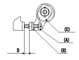
Starting injection quantity adjustment
Adjust the adjusting bolt (A) so that the starting injection quantity is within the standard and fix using the locknut (B).
(C) Stop lever
----------
----------
D=6.0~8.7mm
----------
----------
D=6.0~8.7mm
0000002001 M-CSD ADJUSTMENT
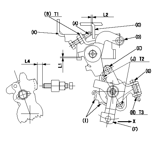
M-CSD adjustment
1. Fixing intermediate lever screw (A) [roller (E) must not contact intermediate lever (D)]
(1)Hold the control lever (C) in the idle position.
(2)Insert a block gauge (thickness gauge) L1 between the intermediate lever (D) and the bracket (K). Adjust screw (A) so that the distance between screw A and the control lever to L2 and fix using the nut (B).
2. Fixing the M-CSD stopper (I)
Pull the CSD lever F in the direction X until it contacts the stopper I and tighten the socket head bolt J when the timer stroke is L3.
3. Screw (G) adjustment
(1)Adjust using the screw G so that the roller E contacts the intermediate lever D, then fix using the nut H.
(2)Pull the CSD lever F in the direction X until it contacts the stopper I and confirm that the control lever shim thickness (lever position) is L4.
Note: Use screw (A) to fine-adjust the lever position. [Maintain a gap L2 between the screw (A) and the control lever (C).]
----------
L1=1+-0.1mm L2=1~2mm L3=0.82+-0.2mm L4=5.2+-0.5mm
----------
L1=1+-0.1mm L2=1~2mm L4=5.2+-0.5mm T1=5.9~8.8N-m(0.6~0.9kgf-m) T2=4.9~6.9N-m(0.5~0.7kgf-m) T3=2.0~2.9N-m(0.2~0.3kgf-m)
----------
L1=1+-0.1mm L2=1~2mm L3=0.82+-0.2mm L4=5.2+-0.5mm
----------
L1=1+-0.1mm L2=1~2mm L4=5.2+-0.5mm T1=5.9~8.8N-m(0.6~0.9kgf-m) T2=4.9~6.9N-m(0.5~0.7kgf-m) T3=2.0~2.9N-m(0.2~0.3kgf-m)
Information:
Start By:a. remove automatic timing advance unit
Keep all parts clean from contaminants. Contaminants put into the system may cause rapid wear and shortened component life.
Before any timing gears are removed, make sure "C" on the crankshaft gear is in alignment with "C" mark on the camshaft gear. 1. Remove bolts, plate (1) and fuel pump idler gear (2). 2. Remove bearing from idler gear (2) with tool (A). 3. Remove four bolts (3) and camshaft gear (4). 4. Remove bolts that are used to fasten shield (5) in position between the fuel pump and the exhaust manifold. Slide shield back from the timing cover plate.5. Remove the three nuts (6). 6. Remove six bolts (7). Remove the timing gear plate and the gasket. The following steps are to install the timing gears and plate.7. Clean the old gasket from the contact surfaces of the timing gear plate and cylinder block. Install a new gasket on the cylinder block. Cut the gasket even with the bottom face of the cylinder block.8. Be sure the O-ring seals are in position on the end of the fuel injection pump housing. Put the timing gear plate in position on the cylinder block and install the six bolts (7). Install nuts (6).
After the timing gear plate is installed, be sure the rack is free to move in the fuel injection pump housing. The O-ring seal on the drive end of the fuel injection pump housing can hold the rack and prevent free rack movement. Rack movement can be seen through hole in the timing gear plate just above where the fuel pump gear is mounted. If the rack does not move freely, remove the timing gear plate and check the O-ring seal on the drive end of the fuel injection pump housing. If the rack does not move freely, the engine can over speed and be damaged. Serious personal injury can be the result.
9. Install camshaft gear (4) with the "C" mark on the camshaft gear in alignment with the "C" mark on the crankshaft gear as shown in the illustration in the Specification section of this manual. Tighten the volts to a torque of 55 7 N m (41 5 lb ft).10. Use tooling (A) to install the bearing in idler gear (2). The end of the bearing must be 1.52 .025 mm (.060 .010 in) below the face of the gear hub.11. Be sure the oil hole in the shaft for gear (2) is open. Install idler gear (2). Put the plate on position with the finished side toward gear (2) and install the bolts.12. Install shield (5) and the four bolts.End By:a. install automatic timing advance unit
Have questions with 104740-2370?
Group cross 104740-2370 ZEXEL
104740-2370
INJECTION-PUMP ASSEMBLY