Information injection-pump assembly
ZEXEL
104740-2320
1047402320

Rating:
Cross reference number
ZEXEL
104740-2320
1047402320
Zexel num
Bosch num
Firm num
Name
104740-2320
INJECTION-PUMP ASSEMBLY
Calibration Data:
Adjustment conditions
Test oil
1404 Test oil ISO4113orSAEJ967d
1404 Test oil ISO4113orSAEJ967d
Test oil temperature
degC
45
45
50
Nozzle
105780-0060
Bosch type code
NP-DN0SD1510
Nozzle holder
105780-2150
Opening pressure
MPa
13
13
13.3
Opening pressure
kgf/cm2
133
133
136
Injection pipe
157805-7320
Injection pipe
Inside diameter - outside diameter - length (mm) mm 2-6-450
Inside diameter - outside diameter - length (mm) mm 2-6-450
Joint assembly
157641-4720
Tube assembly
157641-4020
Transfer pump pressure
kPa
20
20
20
Transfer pump pressure
kgf/cm2
0.2
0.2
0.2
Direction of rotation (viewed from drive side)
Left L
Left L
Injection timing adjustment
Pump speed
r/min
1400
1400
1400
Average injection quantity
mm3/st.
37.2
36.8
37.6
Difference in delivery
mm3/st.
3
Basic
*
Oil temperature
degC
50
48
52
Injection timing adjustment_02
Pump speed
r/min
600
600
600
Average injection quantity
mm3/st.
33.1
30.6
35.6
Oil temperature
degC
50
48
52
Injection timing adjustment_03
Pump speed
r/min
1000
1000
1000
Average injection quantity
mm3/st.
33.3
30.8
35.8
Oil temperature
degC
50
48
52
Injection timing adjustment_04
Pump speed
r/min
1400
1400
1400
Average injection quantity
mm3/st.
37.2
36.2
38.2
Difference in delivery
mm3/st.
3.5
Basic
*
Oil temperature
degC
50
48
52
Injection timing adjustment_05
Pump speed
r/min
1800
1800
1800
Average injection quantity
mm3/st.
37.3
35.3
39.3
Oil temperature
degC
50
48
52
Injection timing adjustment_06
Pump speed
r/min
2400
2400
2400
Average injection quantity
mm3/st.
37.5
35
40
Oil temperature
degC
52
50
54
Injection quantity adjustment
Pump speed
r/min
2700
2700
2700
Average injection quantity
mm3/st.
14
12
16
Difference in delivery
mm3/st.
4.5
Basic
*
Oil temperature
degC
55
52
58
Injection quantity adjustment_02
Pump speed
r/min
2700
2700
2700
Average injection quantity
mm3/st.
14
10.5
17.5
Difference in delivery
mm3/st.
5
Basic
*
Oil temperature
degC
55
52
58
Injection quantity adjustment_03
Pump speed
r/min
2800
2800
2800
Average injection quantity
mm3/st.
5
Oil temperature
degC
55
52
58
Governor adjustment
Pump speed
r/min
400
400
400
Average injection quantity
mm3/st.
10.5
9.5
11.5
Difference in delivery
mm3/st.
2
Basic
*
Oil temperature
degC
48
46
50
Governor adjustment_02
Pump speed
r/min
400
400
400
Average injection quantity
mm3/st.
10.5
8.5
12.5
Difference in delivery
mm3/st.
2.5
Basic
*
Oil temperature
degC
48
46
50
Governor adjustment_03
Pump speed
r/min
750
750
750
Average injection quantity
mm3/st.
5
Oil temperature
degC
50
48
52
Boost compensator adjustment
Pump speed
r/min
700
700
700
Average injection quantity
mm3/st.
16
9.5
22.5
Oil temperature
degC
50
48
52
Lever angle (shim thickness)
mm
5.9
5.9
5.9
Boost compensator adjustment_02
Pump speed
r/min
900
900
900
Average injection quantity
mm3/st.
11.6
4.6
18.6
Oil temperature
degC
50
48
52
Lever angle (shim thickness)
mm
5.9
5.9
5.9
Timer adjustment
Pump speed
r/min
100
100
100
Average injection quantity
mm3/st.
60
50
70
Basic
*
Oil temperature
degC
48
46
50
Remarks
Full
Full
Timer adjustment_02
Pump speed
r/min
100
100
100
Average injection quantity
mm3/st.
60
50
70
Oil temperature
degC
48
46
50
Speed control lever angle
Pump speed
r/min
400
400
400
Average injection quantity
mm3/st.
0
0
0
Oil temperature
degC
48
46
50
Remarks
Magnet OFF at idling position
Magnet OFF at idling position
0000000901
Pump speed
r/min
1000
1000
1000
Overflow quantity
cm3/min
390
260
520
Oil temperature
degC
50
48
52
Stop lever angle
Pump speed
r/min
1000
1000
1000
Pressure
kPa
422
393
451
Pressure
kgf/cm2
4.3
4
4.6
Basic
*
Oil temperature
degC
50
48
52
Stop lever angle_02
Pump speed
r/min
1000
1000
1000
Pressure
kPa
421.5
382
461
Pressure
kgf/cm2
4.3
3.9
4.7
Basic
*
Oil temperature
degC
50
48
52
Stop lever angle_03
Pump speed
r/min
1800
1800
1800
Pressure
kPa
588.5
549
628
Pressure
kgf/cm2
6
5.6
6.4
Oil temperature
degC
50
48
52
Stop lever angle_04
Pump speed
r/min
2400
2400
2400
Pressure
kPa
726
677
775
Pressure
kgf/cm2
7.4
6.9
7.9
Oil temperature
degC
52
50
54
0000001101
Pump speed
r/min
1000
1000
1000
Timer stroke
mm
3
2.8
3.2
Basic
*
Oil temperature
degC
50
48
52
_02
Pump speed
r/min
1000
1000
1000
Timer stroke
mm
3
2.7
3.3
Basic
*
Oil temperature
degC
50
48
52
_03
Pump speed
r/min
1800
1800
1800
Timer stroke
mm
7
6.5
7.5
Oil temperature
degC
50
48
52
_04
Pump speed
r/min
2400
2400
2400
Timer stroke
mm
9.35
8.9
9.8
Oil temperature
degC
52
50
54
0000001201
Max. applied voltage
V
8
8
8
Test voltage
V
13
12
14
Timing setting
K dimension
mm
3.3
3.2
3.4
KF dimension
mm
6.78
6.68
6.88
MS dimension
mm
0.8
0.7
0.9
Control lever angle alpha
deg.
25
23
27
Control lever angle beta
deg.
42
37
47
Test data Ex:
0000001801 M-CSD ADJUSTMENT
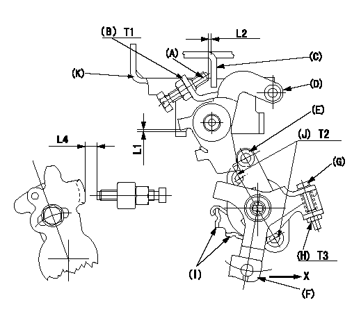
M-CSD adjustment
1. Fixing intermediate lever screw (A) [roller (E) must not contact intermediate lever (D)]
(1)Hold the control lever (C) in the idle position.
(2)Insert a block gauge (thickness gauge) L1 between the intermediate lever (D) and the bracket (K). Adjust screw (A) so that the distance between screw A and the control lever to L2 and fix using the nut (B).
2. Fixing the M-CSD stopper (I)
Pull the CSD lever F in the direction X until it contacts the stopper I and tighten the socket head bolt J when the timer stroke is L3.
3. Screw (G) adjustment
Pull the CSD lever F in the direction X until it contacts the stopper I and adjust using screw G so that the control lever shim thickness is L4. Then fix using nut H.
----------
L1=1+-0.1(mm) L2=1~2(mm) L3=0.82+-0.2(mm) L4=7.1+-0.5(mm)
----------
L1=1+-0.1(mm) L2=1~2(mm) L4=7.1+-0.5(mm) T1=5.9~8.8(N-m)(0.6~0.9(kgf-m)) T2=4.9~6.9(N-m)(0.5~0.7(kgf-m)) T3=2.0~2.9(N-m)(0.2~0.3(kgf-m))
----------
L1=1+-0.1(mm) L2=1~2(mm) L3=0.82+-0.2(mm) L4=7.1+-0.5(mm)
----------
L1=1+-0.1(mm) L2=1~2(mm) L4=7.1+-0.5(mm) T1=5.9~8.8(N-m)(0.6~0.9(kgf-m)) T2=4.9~6.9(N-m)(0.5~0.7(kgf-m)) T3=2.0~2.9(N-m)(0.2~0.3(kgf-m))
Information:
T-T-T Procedure
A torque-turn-tighten (T-T-T) procedure is used in many specifications and instructions.1. Clean the bolt and nut threads.2. Put lubrication of the threads and the seat face of the bolt and nut.3. Turn the bolt or the nut tight according to the torque specification.4. Put a location mark on the part and on the bolt head or nut.5. Turn the bolt or the nut tighter the amount of degrees according to the specifications The side of a nut or bolt head can be used for reference if a mark can not be put on. Torque Wrench Extension
When a torque wrench extension is used with a torque wrench, the torque indication on the torque wrench will be less than the real torque.
(E) Torque wrench drive axis-to-torque wrench extension drive axis. (W) Mark on handle-to-torque wrench drive axis.1. Put a mark on the handle. Measure the handle from the mark to the axis of the torque wrench drive (W).2. Measure the torque wrench extension from the torque wrench drive to the axis of the torque wrench extension drive (E).3. To get correct torque indication (TI) when the real torque (RT) is known: Example: W = 304.8 mm (12 in); E = 65.0 mm (2.56 in); RT (from specifications) = 17 N m (125 lb ft). 4. Hold the torque wrench handle with the longest finger of the hand over the mark on the handle to get the real torque (RT) with low torque indication (TI) on the torque wrench.Locks
Flat metal locks must be installed properly to be effective. Bend one end of the lock around the edge of the part. Bend the other end against one flat surface of the nut of bolt head.Always install new locks in components which house moving parts.If lockwashers are installed on housings made of aluminum, use a flat washer between the lockwasher and the housing. Lines And Wires
When removing or disconnecting a group of lines or wires, tag each one to assure proper assembly.Lubrication
Where applicable, fill the compartments of the components serviced with the amount, type and grade of lubricant recommended in the Operation Maintenance Manual.Rust Preventive Compound
Clean the rust preventive compound from all machined surfaces of new parts before installing the part.Shims
When shims are removed, tie them together and identify them as to location. Keep shims clean and flat until they are reinstalled.Bearings
Anti-Friction Bearings
When an anti-friction bearing is removed, cover it to keep out dirt and abrasives. Wash the bearings in nonflammable cleaning solution and allow them to drain dry. The bearings may be dried with compressed air, but DO NOT SPIN THE BEARING. Discard the bearings if the races and balls or rollers are pitted, scored or burned. If the bearing is serviceable, coat it with oil and wrap it in clean paper. DO NOT unwrap new bearings until time of installation.The life of an anti-friction bearing will be shortened if not properly lubricated.Double Row, Tapered Roller
Double row, tapered roller bearings are precision fit during manufacture and the components are not interchangeable.
Have questions with 104740-2320?
Group cross 104740-2320 ZEXEL
104740-2320
INJECTION-PUMP ASSEMBLY