Information injection-pump assembly
ZEXEL
104740-2300
1047402300

Rating:
Cross reference number
ZEXEL
104740-2300
1047402300
Zexel num
Bosch num
Firm num
Name
104740-2300
INJECTION-PUMP ASSEMBLY
Calibration Data:
Adjustment conditions
Test oil
1404 Test oil ISO4113orSAEJ967d
1404 Test oil ISO4113orSAEJ967d
Test oil temperature
degC
45
45
50
Nozzle
105780-0060
Bosch type code
NP-DN0SD1510
Nozzle holder
105780-2150
Opening pressure
MPa
13
13
13.3
Opening pressure
kgf/cm2
133
133
136
Injection pipe
157805-7320
Injection pipe
Inside diameter - outside diameter - length (mm) mm 2-6-450
Inside diameter - outside diameter - length (mm) mm 2-6-450
Joint assembly
157641-4720
Tube assembly
157641-4020
Transfer pump pressure
kPa
20
20
20
Transfer pump pressure
kgf/cm2
0.2
0.2
0.2
Direction of rotation (viewed from drive side)
Left L
Left L
Injection timing adjustment
Pump speed
r/min
1400
1400
1400
Average injection quantity
mm3/st.
37.2
36.8
37.6
Difference in delivery
mm3/st.
3
Basic
*
Oil temperature
degC
50
48
52
Injection timing adjustment_02
Pump speed
r/min
600
600
600
Average injection quantity
mm3/st.
33.1
30.6
35.6
Oil temperature
degC
50
48
52
Injection timing adjustment_03
Pump speed
r/min
1000
1000
1000
Average injection quantity
mm3/st.
33.3
30.8
35.8
Oil temperature
degC
50
48
52
Injection timing adjustment_04
Pump speed
r/min
1400
1400
1400
Average injection quantity
mm3/st.
37.2
36.2
38.2
Difference in delivery
mm3/st.
3.5
Basic
*
Oil temperature
degC
50
48
52
Injection timing adjustment_05
Pump speed
r/min
1800
1800
1800
Average injection quantity
mm3/st.
37.3
35.3
39.3
Oil temperature
degC
50
48
52
Injection timing adjustment_06
Pump speed
r/min
2400
2400
2400
Average injection quantity
mm3/st.
37.5
35
40
Oil temperature
degC
52
50
54
Injection quantity adjustment
Pump speed
r/min
2700
2700
2700
Average injection quantity
mm3/st.
14
12
16
Difference in delivery
mm3/st.
4.5
Basic
*
Oil temperature
degC
55
52
58
Injection quantity adjustment_02
Pump speed
r/min
2700
2700
2700
Average injection quantity
mm3/st.
14
10.5
17.5
Difference in delivery
mm3/st.
5
Basic
*
Oil temperature
degC
55
52
58
Injection quantity adjustment_03
Pump speed
r/min
2800
2800
2800
Average injection quantity
mm3/st.
5
Oil temperature
degC
55
52
58
Governor adjustment
Pump speed
r/min
350
350
350
Average injection quantity
mm3/st.
10.5
9.5
11.5
Difference in delivery
mm3/st.
2
Basic
*
Oil temperature
degC
48
46
50
Governor adjustment_02
Pump speed
r/min
350
350
350
Average injection quantity
mm3/st.
10.5
8.5
12.5
Difference in delivery
mm3/st.
2.5
Basic
*
Oil temperature
degC
48
46
50
Governor adjustment_03
Pump speed
r/min
700
700
700
Average injection quantity
mm3/st.
5
Oil temperature
degC
50
48
52
Boost compensator adjustment
Pump speed
r/min
700
700
700
Average injection quantity
mm3/st.
16
9.5
22.5
Oil temperature
degC
50
48
52
Lever angle (shim thickness)
mm
7.2
7.2
7.2
Boost compensator adjustment_02
Pump speed
r/min
900
900
900
Average injection quantity
mm3/st.
11.6
4.6
18.6
Oil temperature
degC
50
48
52
Lever angle (shim thickness)
mm
7.2
7.2
7.2
Timer adjustment
Pump speed
r/min
100
100
100
Average injection quantity
mm3/st.
60
50
70
Basic
*
Oil temperature
degC
48
46
50
Remarks
Full
Full
Timer adjustment_02
Pump speed
r/min
100
100
100
Average injection quantity
mm3/st.
60
50
70
Oil temperature
degC
48
46
50
Speed control lever angle
Pump speed
r/min
350
350
350
Average injection quantity
mm3/st.
0
0
0
Oil temperature
degC
48
46
50
Remarks
Magnet OFF at idling position
Magnet OFF at idling position
0000000901
Pump speed
r/min
1000
1000
1000
Overflow quantity
cm3/min
390
260
520
Oil temperature
degC
50
48
52
Stop lever angle
Pump speed
r/min
1000
1000
1000
Pressure
kPa
422
393
451
Pressure
kgf/cm2
4.3
4
4.6
Basic
*
Oil temperature
degC
50
48
52
Stop lever angle_02
Pump speed
r/min
1000
1000
1000
Pressure
kPa
421.5
382
461
Pressure
kgf/cm2
4.3
3.9
4.7
Basic
*
Oil temperature
degC
50
48
52
Stop lever angle_03
Pump speed
r/min
1800
1800
1800
Pressure
kPa
588.5
549
628
Pressure
kgf/cm2
6
5.6
6.4
Oil temperature
degC
50
48
52
Stop lever angle_04
Pump speed
r/min
2400
2400
2400
Pressure
kPa
726
677
775
Pressure
kgf/cm2
7.4
6.9
7.9
Oil temperature
degC
52
50
54
0000001101
Pump speed
r/min
1000
1000
1000
Timer stroke
mm
3
2.8
3.2
Basic
*
Oil temperature
degC
50
48
52
_02
Pump speed
r/min
1000
1000
1000
Timer stroke
mm
3
2.7
3.3
Basic
*
Oil temperature
degC
50
48
52
_03
Pump speed
r/min
1800
1800
1800
Timer stroke
mm
7
6.5
7.5
Oil temperature
degC
50
48
52
_04
Pump speed
r/min
2400
2400
2400
Timer stroke
mm
9.35
8.9
9.8
Oil temperature
degC
52
50
54
0000001201
Max. applied voltage
V
8
8
8
Test voltage
V
13
12
14
Timing setting
K dimension
mm
3.3
3.2
3.4
KF dimension
mm
6.78
6.68
6.88
MS dimension
mm
0.8
0.7
0.9
Control lever angle alpha
deg.
25
23
27
Control lever angle beta
deg.
44
39
49
Test data Ex:
0000001801 M-CSD ADJUSTMENT
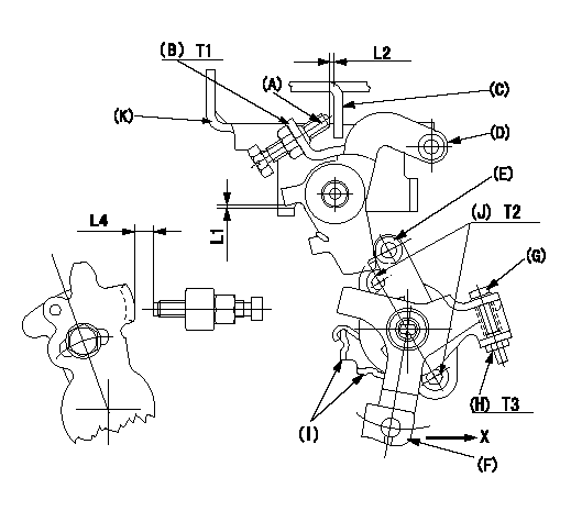
M-CSD adjustment
1. Fixing intermediate lever screw (A) [roller (E) must not contact intermediate lever (D)]
(1)Hold the control lever (C) in the idle position.
(2)Insert a block gauge (thickness gauge) L1 between the intermediate lever (D) and the bracket (K). Adjust screw (A) so that the distance between screw A and the control lever to L2 and fix using the nut (B).
2. Fixing the M-CSD stopper (I)
Pull the CSD lever F in the direction X until it contacts the stopper I and tighten the socket head bolt J when the timer stroke is L3.
3. Screw (G) adjustment
Pull the CSD lever F in the direction X until it contacts the stopper I and adjust using screw G so that the control lever shim thickness is L4. Then fix using nut H.
----------
L1=1+-0.1(mm) L2=1~2(mm) L3=0.82+-0.2(mm) L4=7.1+-0.5(mm)
----------
L1=1+-0.1(mm) L2=1~2(mm) L4=7.1+-0.5(mm) T1=5.9~8.8(N-m)(0.6~0.9(kgf-m)) T2=4.9~6.9(N-m)(0.5~0.7(kgf-m)) T3=2.0~2.9(N-m)(0.2~0.3(kgf-m))
----------
L1=1+-0.1(mm) L2=1~2(mm) L3=0.82+-0.2(mm) L4=7.1+-0.5(mm)
----------
L1=1+-0.1(mm) L2=1~2(mm) L4=7.1+-0.5(mm) T1=5.9~8.8(N-m)(0.6~0.9(kgf-m)) T2=4.9~6.9(N-m)(0.5~0.7(kgf-m)) T3=2.0~2.9(N-m)(0.2~0.3(kgf-m))
0000001901 DASHPOT ADJUSTMENT
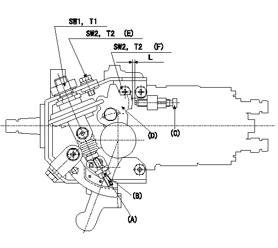
Adjustment of the dash pot
1. Insert a block gauge L (thickness gauge) between the idle set screw (C) and the control lever (D).
2. In the above condition, adjust so that the dashpot adjusting screw (A) contacts the pushrod. Then, fix using the locknut (B) (Tightening torque T3).
3. Confirm that the control lever returns to the idling position without the adjusting screw or dashpot sticking or coming loose.
(E) 5 locations
(F) 4 locations
----------
L=6.0+-0.05(mm) T3=4.9~6.9(N-m)(0.5~0.7(kgf-m))
----------
SW1=22(mm) SW2=10(mm) T1=14.7~19.6(N-m)(1.5~2.0(kgf-m)) T2=5.9~8.8(N-m)(0.6~0.9(kgf-m)) L=6.0+-0.05(mm)
----------
L=6.0+-0.05(mm) T3=4.9~6.9(N-m)(0.5~0.7(kgf-m))
----------
SW1=22(mm) SW2=10(mm) T1=14.7~19.6(N-m)(1.5~2.0(kgf-m)) T2=5.9~8.8(N-m)(0.6~0.9(kgf-m)) L=6.0+-0.05(mm)
Information:
Possible Causes/Corrections Air Or Water In Fuel SystemWith air in the fuel system, the engine will normally be difficult to start, run rough, and release a large amount of white smoke. If the engine will not start, loosen a fuel injection line nut at the through the head adapter and crank the engine until fuel comes out. Tighten the fuel line nut. Start the engine. If the engine does not run smooth or releases a large amount of white smoke, loosen the fuel line nuts one at a time at the through the head adapters until the fuel that comes out is free of air. Tighten the fuel line nuts. If the air cannot be removed in this way, put 35 kPa (5 psi) of air pressure to the fuel tank.
Do not use more than 55 kPa (8 psi) of air pressure in the fuel tank or damage to the tank may result.
Check for leaks at the connection between the fuel tank and the fuel transfer pump. If leaks are found, tighten the connections or replace the lines. If there are no visual leaks, remove the fuel supply line from the tank and connect it to an outside furl supply. If this corrects the problem, the suction line (standpipe) inside the fuel tank has a leak.Water in the fuel can cause rough running and possible fuel system damage. Valve Adjustment Not CorrectCheck and make necessary adjustments as in Testing And Adjusting Section of the Service Manual. Intake valve lash is 0.38 mm (.015 in) and exhaust valve lash is 0.64 mm (.025 in). Also check for a bent or broken push rod. Defective Fuel Nozzle(s)Find a defective nozzle by running engine at the rpm where it runs rough. Loosen the fuel line nut at the through the head adapter enough to stop fuel supply to that cylinder. Each cylinder must be checked this way. If a cylinder is found where loosening of the nut makes no difference in the rough running, test the nozzle for that cylinder. To test a nozzle, remove the nozzle from the engine and test as in Testing and Adjusting Section of this Service Manual. Fuel Leakage From Fuel Injection Line NutTighten nut to 40 7 N m (30 5 lb ft). Again check for leakage. Be sure to check fuel injection lines inside valve cover base. Defective Fuel Injection PumpAn injection pump can have a good fuel flow coming from it but cause rough running because of slow timing that is caused by wear on the bottom end of the plunger. See the Testing and Adjusting Section in this Service Manual for the correct specifications and procedure to check plungers and lifters.Fuel pumps which are severely scored from debris can cause rough running but fuel dilution usually occurs before horsepower is affected.Low installation torque on the fuel pump retaining nut can cause misfire, rough running and low power. Fuel Has A High "Cloud Point"In cold weather operation this condition should
Have questions with 104740-2300?
Group cross 104740-2300 ZEXEL
104740-2300
INJECTION-PUMP ASSEMBLY