Information injection-pump assembly
ZEXEL
104740-2280
1047402280
Rating:
Cross reference number
ZEXEL
104740-2280
1047402280
Zexel num
Bosch num
Firm num
Name
104740-2280
INJECTION-PUMP ASSEMBLY
Calibration Data:
Adjustment conditions
Test oil
1404 Test oil ISO4113orSAEJ967d
1404 Test oil ISO4113orSAEJ967d
Test oil temperature
degC
45
45
50
Nozzle
105780-0060
Bosch type code
NP-DN0SD1510
Nozzle holder
105780-2150
Opening pressure
MPa
13
13
13.3
Opening pressure
kgf/cm2
133
133
136
Injection pipe
157805-7320
Injection pipe
Inside diameter - outside diameter - length (mm) mm 2-6-450
Inside diameter - outside diameter - length (mm) mm 2-6-450
Joint assembly
157641-4720
Tube assembly
157641-4020
Transfer pump pressure
kPa
20
20
20
Transfer pump pressure
kgf/cm2
0.2
0.2
0.2
Direction of rotation (viewed from drive side)
Left L
Left L
Injection timing adjustment
Pump speed
r/min
1400
1400
1400
Average injection quantity
mm3/st.
31
30.6
31.4
Difference in delivery
mm3/st.
2
Basic
*
Oil temperature
degC
50
48
52
Injection timing adjustment_02
Pump speed
r/min
600
600
600
Average injection quantity
mm3/st.
30.4
28.4
32.4
Oil temperature
degC
50
48
52
Injection timing adjustment_03
Pump speed
r/min
1000
1000
1000
Average injection quantity
mm3/st.
29.3
27.3
31.3
Oil temperature
degC
50
48
52
Injection timing adjustment_04
Pump speed
r/min
1400
1400
1400
Average injection quantity
mm3/st.
32
31
33
Difference in delivery
mm3/st.
2.5
Basic
*
Oil temperature
degC
50
48
52
Injection timing adjustment_05
Pump speed
r/min
1800
1800
1800
Average injection quantity
mm3/st.
30.8
28.8
32.8
Oil temperature
degC
50
48
52
Injection timing adjustment_06
Pump speed
r/min
2400
2400
2400
Average injection quantity
mm3/st.
30.8
28.8
32.8
Oil temperature
degC
52
50
54
Injection quantity adjustment
Pump speed
r/min
2700
2700
2700
Average injection quantity
mm3/st.
14.8
12.8
16.8
Difference in delivery
mm3/st.
4.5
Basic
*
Oil temperature
degC
55
52
58
Injection quantity adjustment_02
Pump speed
r/min
2700
2700
2700
Average injection quantity
mm3/st.
14.8
11.3
18.3
Difference in delivery
mm3/st.
5
Basic
*
Oil temperature
degC
55
52
58
Injection quantity adjustment_03
Pump speed
r/min
2900
2900
2900
Average injection quantity
mm3/st.
6
Oil temperature
degC
55
52
58
Governor adjustment
Pump speed
r/min
350
350
350
Average injection quantity
mm3/st.
9.6
8.6
10.6
Difference in delivery
mm3/st.
2
Basic
*
Oil temperature
degC
48
46
50
Governor adjustment_02
Pump speed
r/min
350
350
350
Average injection quantity
mm3/st.
9.6
7.6
11.6
Difference in delivery
mm3/st.
2.5
Basic
*
Oil temperature
degC
48
46
50
Governor adjustment_03
Pump speed
r/min
600
600
600
Average injection quantity
mm3/st.
3
Oil temperature
degC
50
48
52
Boost compensator adjustment
Pump speed
r/min
700
700
700
Average injection quantity
mm3/st.
13.5
7
20
Oil temperature
degC
50
48
52
Lever angle (shim thickness)
mm
7
7
7
Boost compensator adjustment_02
Pump speed
r/min
900
900
900
Oil temperature
degC
50
48
52
Lever angle (shim thickness)
mm
7
7
7
Remarks
MEASURE
MEASURE
Timer adjustment
Pump speed
r/min
100
100
100
Average injection quantity
mm3/st.
65
55
75
Basic
*
Oil temperature
degC
48
46
50
Timer adjustment_02
Pump speed
r/min
100
100
100
Average injection quantity
mm3/st.
65
55
75
Oil temperature
degC
48
46
50
Speed control lever angle
Pump speed
r/min
350
350
350
Average injection quantity
mm3/st.
0
0
0
Oil temperature
degC
48
46
50
Remarks
Magnet OFF at idling position
Magnet OFF at idling position
0000000901
Pump speed
r/min
1000
1000
1000
Overflow quantity with S/T ON
cm3/min
440
310
570
Oil temperature
degC
50
48
52
Stop lever angle
Pump speed
r/min
1000
1000
1000
Pressure with S/T ON
kPa
412
383
441
Pressure with S/T ON
kgf/cm2
4.2
3.9
4.5
Pressure with S/T OFF
kPa
353
304
402
Pressure with S/T OFF
kgf/cm2
3.6
3.1
4.1
Basic
*
Oil temperature
degC
50
48
52
Remarks
ON
ON
Stop lever angle_02
Pump speed
r/min
1000
1000
1000
Pressure
kPa
412
373
451
Pressure
kgf/cm2
4.2
3.8
4.6
Basic
*
Oil temperature
degC
50
48
52
Stop lever angle_03
Pump speed
r/min
1400
1400
1400
Pressure
kPa
510
471
549
Pressure
kgf/cm2
5.2
4.8
5.6
Oil temperature
degC
50
48
52
Stop lever angle_04
Pump speed
r/min
2400
2400
2400
Pressure
kPa
735.5
696
775
Pressure
kgf/cm2
7.5
7.1
7.9
Oil temperature
degC
52
50
54
0000001101
Pump speed
r/min
1000
1000
1000
Timer stroke with S/T ON
mm
4.4
4.2
4.6
Timer stroke with S/T OFF
mm
3.2
2.8
3.6
Basic
*
Oil temperature
degC
50
48
52
Remarks
ON
ON
_02
Pump speed
r/min
1000
1000
1000
Timer stroke
mm
4.4
4.1
4.7
Basic
*
Oil temperature
degC
50
48
52
_03
Pump speed
r/min
1400
1400
1400
Timer stroke
mm
6.4
5.9
6.9
Oil temperature
degC
50
48
52
_04
Pump speed
r/min
2400
2400
2400
Timer stroke
mm
10.65
10.2
11.1
Oil temperature
degC
50
48
52
0000001201
Max. applied voltage
V
8
8
8
Test voltage
V
13
12
14
Timing setting
K dimension
mm
3.3
3.2
3.4
KF dimension
mm
6.78
6.68
6.88
MS dimension
mm
0.8
0.7
0.9
Control lever angle alpha
deg.
25
23
27
Control lever angle beta
deg.
44
39
49
Test data Ex:
0000001801 POTENTIOMETER ADJUSTMENT
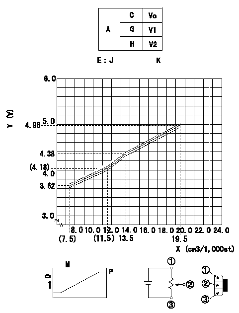
Adjustment of the potentiometer
Adjusting method (dummy bolt method):
1. Adjust at boost pressure P = P1 {P2}.
2. Position the control lever at the adjusting point in the table, hold the dummy bolt against the lever and then fix.
3. Install the potentiometer so that the output voltage is V3 (applied voltage Vi) at the fixed point.
4. After completing potentiometer installation, remove the dummy bolt.
In the following condition, change the installation position of the potentiometer to adjust the output voltage to within the specified values.
Measure the injection quantity at control lever position a (shim thickness = approximately L mm) at N = N1 r/min, determine the voltage using the formula, and adjust the potentiometer.
A:Adjustment conditions
B:Adjustment value
C:Position of the control lever
N:Pump speed
Q:Injection quantity
Vo:Output voltage
E:Conversion formula
F:Adjusting point
G:Idle
H:Full speed
K:Applied voltage
X:Injection quantity (cm3/1,000st)
Y:Voltage (V)
----------
N1=700r/min a=11deg L=7.0mm
----------
V1=Measure V2=Measure J:7.5<=X<=11.5cm3/1000st V+-0.03=0.01346X+2.634 11.5<=X<=19.5cm3/1000st V+-0.03=0.0977X+3.059 K=10V
----------
N1=700r/min a=11deg L=7.0mm
----------
V1=Measure V2=Measure J:7.5<=X<=11.5cm3/1000st V+-0.03=0.01346X+2.634 11.5<=X<=19.5cm3/1000st V+-0.03=0.0977X+3.059 K=10V
0000001901 W-CSD ADJUSTMENT
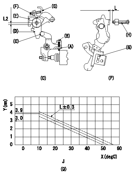
Adjustment of the W-CSD
1. Setting the intermediate lever position (Refer to Fig. 1(O), 2(P).)
(1)Insert a block gauge L1 between the idling set screw (H) and the control lever (G).
(2)Insert a shim of thickness L2 mm between the intermediate lever (D) and the intermediate lever bracket (E). Ensure the screw (F) contacts the control lever (G), then fix the nut.
2. Adjustment of the W-CSD lever (Refer to Fig. 1(O), 2(P).)
(1)Insert a block gauge L3 determined from the graph (L-t) in figure 3 (Q) between the idling set screw (H) and the control lever (G).
(2)Adjust screw B until the W-CSD lever C's roller contacts the intermediate lever D. Then, fix using locknut A.
Note:
The temperature of the wax at adjustment must not exceed a.
X:Temperature t
Y:Control lever L dimension (control lever position)
J:Graph L-t
----------
L1=L=3.0+-0.05mm L2=5.3+-0.05mm L3=L+-0.05mm a=30degC
----------
L1=3.0+-0.05mm L2=5.3mm J=t(degC)??10?FL=3.9 10??t(degC)??30:L=-0.09t+4.8 30??t(degC)??54.3:L=-0.086t+4.68
----------
L1=L=3.0+-0.05mm L2=5.3+-0.05mm L3=L+-0.05mm a=30degC
----------
L1=3.0+-0.05mm L2=5.3mm J=t(degC)??10?FL=3.9 10??t(degC)??30:L=-0.09t+4.8 30??t(degC)??54.3:L=-0.086t+4.68
0000002001 DASHPOT ADJUSTMENT
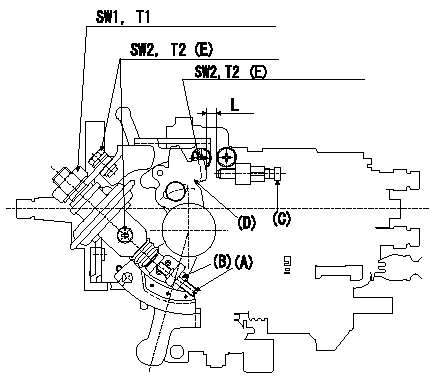
Adjustment of the dash pot
1. Insert a block gauge L (thickness gauge) between the idle set screw (C) and the control lever (D).
2. In the above condition, adjust the position of the dash pot so that the dash pot adjustment screw (A) contacts the push rod and then fix the screw using the nut (B).
T3T3
Note:
(1)The adjusting screw and pushrod contact faces must be smooth.
(2)Confirm that the control lever returns to the idling position.
(E): 2 locations
----------
T3=4.9~7N-m(0.5~0.7kgf-m) L=6.0+-0.05mm
----------
T1=15.0~20.0N-m{1.5~2.0kgf-m} T2=6.0~9.0N-m{0.6~0.9kgf-m} SW1=22mm SW2=10mm L=6.0+-0.05mm
----------
T3=4.9~7N-m(0.5~0.7kgf-m) L=6.0+-0.05mm
----------
T1=15.0~20.0N-m{1.5~2.0kgf-m} T2=6.0~9.0N-m{0.6~0.9kgf-m} SW1=22mm SW2=10mm L=6.0+-0.05mm
Information:
Starting Motor
The starting motor is used to turn the engine flywheel fast enough to get the engine to start running.The starting motor has a solenoid. When the start switch is activated, the solenoid will move the starting motor pinion to engage it with the ring gear on the flywheel of the engine. The starting motor pinion will engage with the ring gear before the electric contacts in the solenoid close the circuit between the battery and the starting motor. When the circuit between the battery and the starting motor is complete, the pinion will turn the engine flywheel. A clutch gives protection for the starting motor so that the engine cannot turn the starting motor too fast. When the start switch is released, the starting motor pinion will move away from the ring gear.
Starting Motor Cross Section
(1) Field. (2) Solenoid. (3) Clutch. (4) Pinion. (5) Commutator. (6) Brush assembly. (7) Armature.Other Components
Circuit Breaker
Circuit Breaker Schematic
(1) Reset button. (2) Disc in open position. (3) Contacts. (4) Disc. (5) Battery circuit terminals.The circuit breaker is a switch that opens the battery circuit if the current in the electrical system goes higher than the rating of the circuit breaker.A heat activated metal disc with a contact point makes complete the electric circuit through the circuit breaker. If the current in the electrical system gets too high, it causes the metal disc to get hot. This heat causes a distortion of the metal disc which opens the contacts and breaks the circuit. A circuit breaker that is open can be reset (an adjustment to make the circuit complete again) after it becomes cool. Push the reset button to close the contacts and reset the circuit breaker.Compression Brake
The compression brake permits the operator to control the speed of the vehicle on grades, curves, or anytime when speed reduction is necessary, but long applications of the service brakes are not desired. In downhill operation, or any slow down condition, the engine crankshaft is turned by the rear wheels (through the differential, driveshaft, transmission and clutch). To reduce the speed of the vehicle, an application of a braking force can be made to the pistons of the engine.The compression brake, when activated, does this through the conversion of the engine from a source of power to an air compressor that absorbs (takes) power. This conversion is made possible by a master to slave piston arrangement, where movement of the rocker arm for the exhaust valve of one cylinder is transferred hydraulically to open the exhaust valve of another cylinder near the top of its normal compression stroke cycle. The compressed cylinder charge is now released into the exhaust manifold.The release of the compressed air pressure to the atmosphere prevents the return of energy to the engine piston on the expansion (power) stroke. The result is an energy loss, since the work done by the compression of the cylinder charge is not returned by the expansion process. This energy loss is taken from the rear wheels,
Have questions with 104740-2280?
Group cross 104740-2280 ZEXEL
104740-2280
INJECTION-PUMP ASSEMBLY