Information injection-pump assembly
BOSCH
9 460 610 514
9460610514
ZEXEL
104740-2204
1047402204
Rating:
Cross reference number
BOSCH
9 460 610 514
9460610514
ZEXEL
104740-2204
1047402204
Zexel num
Bosch num
Firm num
Name
Calibration Data:
Adjustment conditions
Test oil
1404 Test oil ISO4113orSAEJ967d
1404 Test oil ISO4113orSAEJ967d
Test oil temperature
degC
45
45
50
Nozzle
105780-0060
Bosch type code
NP-DN0SD1510
Nozzle holder
105780-2150
Opening pressure
MPa
13
13
13.3
Opening pressure
kgf/cm2
133
133
136
Injection pipe
157805-7320
Injection pipe
Inside diameter - outside diameter - length (mm) mm 2-6-450
Inside diameter - outside diameter - length (mm) mm 2-6-450
Joint assembly
157641-4720
Tube assembly
157641-4020
Transfer pump pressure
kPa
20
20
20
Transfer pump pressure
kgf/cm2
0.2
0.2
0.2
Direction of rotation (viewed from drive side)
Left L
Left L
Injection timing adjustment
Pump speed
r/min
1400
1400
1400
Average injection quantity
mm3/st.
36.6
36.2
37
Difference in delivery
mm3/st.
3
Basic
*
Oil temperature
degC
50
48
52
Injection timing adjustment_02
Pump speed
r/min
600
600
600
Average injection quantity
mm3/st.
32.3
29.8
34.8
Oil temperature
degC
50
48
52
Injection timing adjustment_03
Pump speed
r/min
1000
1000
1000
Average injection quantity
mm3/st.
31.9
29.4
34.4
Oil temperature
degC
50
48
52
Injection timing adjustment_04
Pump speed
r/min
1400
1400
1400
Average injection quantity
mm3/st.
36.6
35.6
37.6
Difference in delivery
mm3/st.
3.5
Basic
*
Oil temperature
degC
50
48
52
Injection timing adjustment_05
Pump speed
r/min
1800
1800
1800
Average injection quantity
mm3/st.
37.5
35
40
Oil temperature
degC
50
48
52
Injection quantity adjustment
Pump speed
r/min
2700
2700
2700
Average injection quantity
mm3/st.
14
12
16
Difference in delivery
mm3/st.
4.5
Basic
*
Oil temperature
degC
55
52
58
Injection quantity adjustment_02
Pump speed
r/min
2800
2800
2800
Average injection quantity
mm3/st.
5
Oil temperature
degC
55
52
58
Injection quantity adjustment_03
Pump speed
r/min
2400
2400
2400
Average injection quantity
mm3/st.
37.1
34.1
40.1
Oil temperature
degC
52
50
54
Governor adjustment
Pump speed
r/min
400
400
400
Average injection quantity
mm3/st.
10.5
9.5
11.5
Difference in delivery
mm3/st.
2
Basic
*
Oil temperature
degC
48
46
50
Governor adjustment_02
Pump speed
r/min
400
400
400
Average injection quantity
mm3/st.
10.5
8.5
12.5
Difference in delivery
mm3/st.
2.5
Basic
*
Oil temperature
degC
48
46
50
Governor adjustment_03
Pump speed
r/min
750
750
750
Average injection quantity
mm3/st.
5
Oil temperature
degC
50
48
52
Boost compensator adjustment
Pump speed
r/min
700
700
700
Average injection quantity
mm3/st.
18
11.5
24.5
Oil temperature
degC
50
48
52
Lever angle (shim thickness)
mm
5.9
5.9
5.9
Remarks
From idle
From idle
Boost compensator adjustment_02
Pump speed
r/min
900
900
900
Average injection quantity
mm3/st.
14.2
7.2
21.2
Oil temperature
degC
50
48
52
Lever angle (shim thickness)
mm
5.9
5.9
5.9
Remarks
From idle
From idle
Timer adjustment
Pump speed
r/min
100
100
100
Average injection quantity
mm3/st.
60
50
70
Basic
*
Oil temperature
degC
48
46
50
Remarks
Full
Full
Speed control lever angle
Pump speed
r/min
400
400
400
Average injection quantity
mm3/st.
0
0
0
Oil temperature
degC
48
46
50
Remarks
Magnet OFF at idling position
Magnet OFF at idling position
0000000901
Pump speed
r/min
1000
1000
1000
Overflow quantity
cm3/min
390
260
520
Oil temperature
degC
50
48
52
Stop lever angle
Pump speed
r/min
1000
1000
1000
Pressure
kPa
412
383
441
Pressure
kgf/cm2
4.2
3.9
4.5
Basic
*
Oil temperature
degC
50
48
52
Stop lever angle_02
Pump speed
r/min
1000
1000
1000
Pressure
kPa
412.5
375
450
Pressure
kgf/cm2
4.2
3.8
4.6
Basic
*
Oil temperature
degC
50
48
52
Stop lever angle_03
Pump speed
r/min
1800
1800
1800
Pressure
kPa
588.5
549
628
Pressure
kgf/cm2
6
5.6
6.4
Oil temperature
degC
50
48
52
Stop lever angle_04
Pump speed
r/min
2400
2400
2400
Pressure
kPa
735.5
686
785
Pressure
kgf/cm2
7.5
7
8
Oil temperature
degC
52
50
54
0000001101
Pump speed
r/min
1000
1000
1000
Timer stroke
mm
3.1
2.9
3.3
Basic
*
Oil temperature
degC
50
48
52
_02
Pump speed
r/min
1000
1000
1000
Timer stroke
mm
3.1
2.8
3.4
Basic
*
Oil temperature
degC
50
48
52
_03
Pump speed
r/min
1800
1800
1800
Timer stroke
mm
6.8
6.3
7.3
Oil temperature
degC
50
48
52
_04
Pump speed
r/min
2400
2400
2400
Timer stroke
mm
8.55
8.1
9
Oil temperature
degC
52
50
54
0000001201
Max. applied voltage
V
8
8
8
Test voltage
V
13
12
14
Timing setting
K dimension
mm
3.3
3.2
3.4
KF dimension
mm
6.78
6.68
6.88
MS dimension
mm
0.8
0.7
0.9
Control lever angle alpha
deg.
25
23
27
Control lever angle beta
deg.
42
37
47
Test data Ex:
0000001801 W-CSD ADJUSTMENT
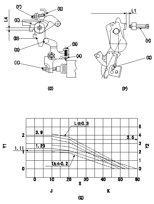
Adjustment of the W-CSD
1. Adjustment of the advance angle of the timer
(1)Determine the timer advance angle from the graph in Fig. 3 (Q).
(2)(1) Adjust using the screw (I) so that the timer advance angle determined in item (1) is obtained.
2. Setting the intermediate lever position (refer to fig 1 and fig 2)
(1)Insert a block gauge L1 between the idling set screw (H) and the control lever (G).
(2)Insert a shim of thickness L2 mm between the intermediate lever (D) and the intermediate lever bracket (E). Ensure the screw (F) contacts the control lever (G), then fix the nut.
3. W-CSD lever adjustment [refer to fig 1 (O) and fig 2 (P)]
(1)After completing (2) above, remove the block gauge L3 and the shim with the thickness L4.
(2)Insert a block gauge L5 determined from the graph (L-theta) in figure 3 (Q) between the idling set screw (H) and the control lever (G).
(3)Adjust the screw (B) until the screw (F) contacts the control lever (G). Then fix locknut (A).
Note:
The temperature of the wax at adjustment must not exceed a.
X:Temperature theta (deg C)
Y1:Timer stroke TA (mm)
Y2:Control lever L dimension (mm; control lever position)
J:TA-theta line
theta (deg C) <= 10: TA = 1.23
10 <= theta (deg C) <= 20: TA = -0.012 theta + 1.35
20 <= theta (deg C) <= 53.6: TA = -0.0330 theta + 1.77
K:L-theta graph
theta (deg C) <= 10: L = 3.9
10 <= theta (deg C) <= 20: L = -0.04 theta + 4.3
20 <= theta (deg C) <= 52.3: L = -0.108 theta + 5.66
----------
L1=3.5+-0.05mm L2=5.3+-0.05mm L3=3.5mm L4=5.3mm L5=L1+-0.05mm a=30degC
----------
L1=3.5+-0.05mm L4=5.3mm
----------
L1=3.5+-0.05mm L2=5.3+-0.05mm L3=3.5mm L4=5.3mm L5=L1+-0.05mm a=30degC
----------
L1=3.5+-0.05mm L4=5.3mm
0000001901 IDLING SWITCH ADJUSTMENT
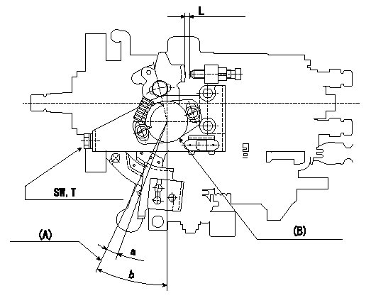
Idle switch adjustment
ON - OFF changeover point: from idle to a (shim thickness L)
Idle-c: ON
d ~ full speed: OFF
(A) = idle lever position
(B) = idle switch (potentiometer)
----------
a=5deg+-1deg c=5deg d=5deg L=3.3+-0.05mm
----------
a=5deg+-1deg b=(25deg+-2deg) L=3.3+-0.05mm SW=SW10mm T=6~9N-m{0.6~0.9kgf-m}
----------
a=5deg+-1deg c=5deg d=5deg L=3.3+-0.05mm
----------
a=5deg+-1deg b=(25deg+-2deg) L=3.3+-0.05mm SW=SW10mm T=6~9N-m{0.6~0.9kgf-m}
Information:
Keep all parts clean from contaminants. Contaminants put into the system may cause rapid wear and shortened component life.
1. Turn the crankshaft until the "C" mark on the crankshaft gear is in alignment with the "C" mark on the camshaft gear. To keep the engine timing correct during removal and installation of the camshaft, put a mark on the teeth of the fuel injection pump drive gear and idler gear at location (A). Put a mark on the teeth of the idler gear and camshaft gear at location (B). When installing the camshaft, the engine timing will be correct when the marks at locations (A) and (B) are in alignment and the "C" marks on the crankshaft and camshaft gears are in alignment.2. Remove the bolts, lock and washer (1) that hold the camshaft in position.
Do not cause damage to the lobes or bearings when the camshaft is removed.
3. Remove the camshaft and gear (2).4. If necessary, remove the bolts and gear. The following steps are for the installation of the camshaft.5. Put the camshaft drive gear in position on the end of the camshaft, and install the bolts that hold it. Tighten the bolts to a torque of 55 7 N m (41 5 lb ft).
Do not cause damage to the lobes or bearings when the camshaft is installed.
6. Put 2P2506 Thread Lubricant on the camshaft lobes only, and clean engine oil on the bearing journals. Install camshaft (3) aligning the "C" marks and the marks put on the gears during removal.7. Install washer (1), the lock and bolts.End By:a. install valve liftersb. install timing gear cover
Perform Scheduled Oil Sampling on oil wetted compartments after performing service work to check for contaminants left in the system following repair. Contaminants put into the system may cause rapid wear and shortened component life.