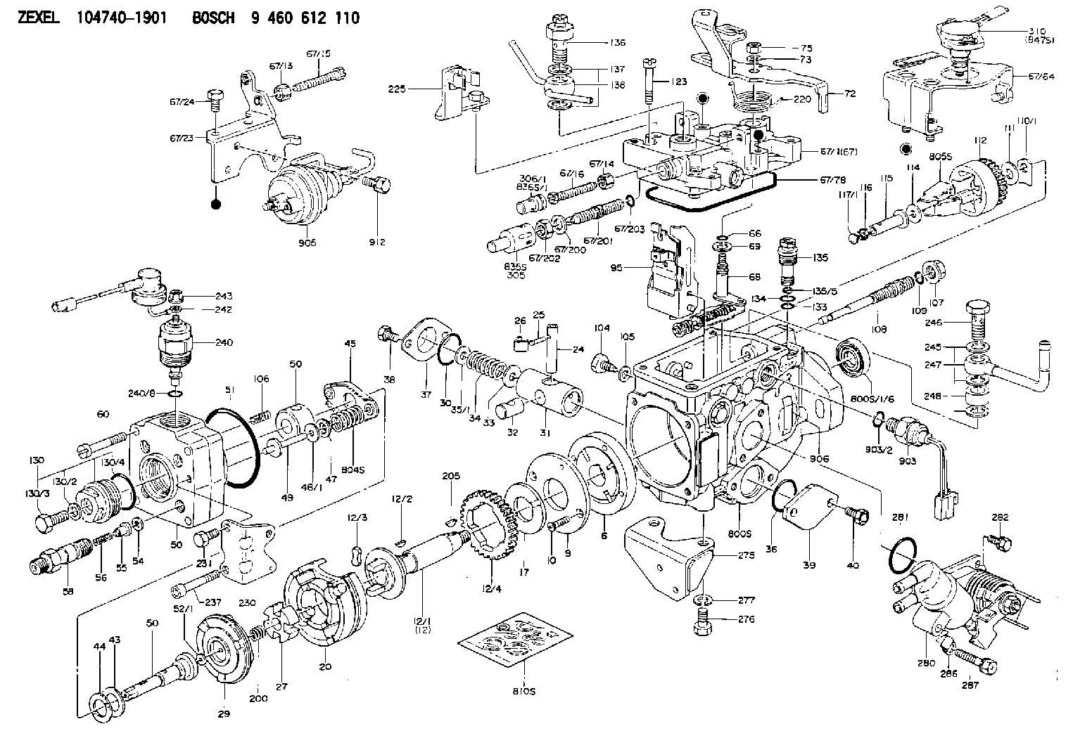
Information injection-pump assembly
BOSCH
9 460 612 110
9460612110
ZEXEL
104740-1901
1047401901
ISUZU
8970255471
8970255471

Rating:
Components :
| 0. | INJECTION-PUMP ASSEMBLY | 104740-1901 |
| 1. | _ | |
| 2. | FUEL INJECTION PUMP | 104640-1901 |
| 3. | NUMBER PLATE | 146920-7600 |
| 4. | _ | 146672-5820 |
| 5. | CAPSULE | |
| 6. | ADJUSTING DEVICE | 146620-4720 |
| 7. | NOZZLE AND HOLDER ASSY | 105158-2182 |
| 8. | Nozzle and Holder | 8-94470-499-1 |
| 9. | Open Pre:MPa(Kqf/cm2) | 13.2{135} |
| 10. | NOZZLE-HOLDER | 105088-1090 |
| 11. | NOZZLE | 105007-1100 |
Scheme ###:
| 1/6. | [1] | 146601-0700 | PACKING RING |
| 6. | [1] | 146100-0120 | SUPPLY PUMP |
| 9. | [1] | 146103-0000 | COVER |
| 10. | [2] | 139104-0000 | FLAT-HEAD SCREW |
| 12. | [1] | 146200-0320 | DRIVE SHAFT |
| 12/1. | [1] | 146200-0300 | DRIVE SHAFT |
| 12/2. | [1] | 146201-0000 | WOODRUFF KEY |
| 12/3. | [2] | 146202-0100 | DAMPER |
| 12/4. | [1] | 146203-0000 | TOOTHED GEAR |
| 17. | [1] | 146204-0000 | PLAIN WASHER |
| 20. | [1] | 146210-1920 | ROLLER SET |
| 24. | [1] | 146303-0100 | BEARING PIN |
| 25. | [1] | 146304-0000 | BEARING PIN |
| 26. | [1] | 146305-0000 | CLAMPING BAND |
| 27. | [1] | 146205-0000 | SLOTTED WASHER |
| 29. | [1] | 146220-0020 | CAM PLATE |
| 30. | [1] | 146600-0800 | O-RING |
| 31. | [1] | 146300-0500 | PUMP PLUNGER |
| 32. | [1] | 146301-0000 | SLIDING PIECE |
| 33. | [1] | 146603-0700 | SHIM D17.5&7.5T0.60 |
| 34. | [1] | 146302-8400 | COMPRESSION SPRING |
| 34B. | [1] | 146302-9600 | COMPRESSION SPRING |
| 34C. | [1] | 146302-9700 | COMPRESSION SPRING |
| 35/1. | [0] | 146603-0700 | SHIM D17.5&7.5T0.60 |
| 35/1. | [0] | 146603-0800 | SHIM D17.5&7.5T0.70 |
| 35/1. | [0] | 146603-0900 | SHIM D17.5&7.5T0.90 |
| 35/1. | [0] | 146603-1000 | SHIM D17.5&7.5T1.00 |
| 35/1. | [0] | 146603-1100 | SHIM D17.5&7.5T1.20 |
| 35/1. | [0] | 146603-3600 | SHIM D17.5&7.5T2.40 |
| 36. | [1] | 146600-0800 | O-RING |
| 37. | [1] | 146310-0700 | COVER |
| 38. | [2] | 146620-5000 | BLEEDER SCREW |
| 39. | [1] | 146310-0100 | COVER |
| 40. | [2] | 146620-5000 | BLEEDER SCREW |
| 43. | [1] | 146230-0000 | SHIM |
| 44. | [1] | 146230-0100 | PLAIN WASHER |
| 45. | [1] | 146231-0001 | SLOTTED WASHER |
| 47. | [2] | 146233-0000 | SLOTTED WASHER |
| 48/1. | [1] | 146603-0000 | SHIM D17.0&5.2T0.50 |
| 48/1. | [1] | 146603-0100 | SHIM D17.0&5.2T0.80 |
| 48/1. | [1] | 146603-0200 | SHIM D17.0&5.2T1.00 |
| 48/1. | [1] | 146603-0300 | SHIM D17.0&5.2T1.20 |
| 48/1. | [1] | 146603-0400 | SHIM D17.0&5.2T1.50 |
| 48/1. | [1] | 146603-0500 | SHIM D17.0&5.2T1.80 |
| 48/1. | [1] | 146603-0600 | SHIM D17.0&5.2T2.00 |
| 48/1. | [1] | 146690-1400 | SHIM D17&5.2T0.9 |
| 48/1. | [1] | 146690-1500 | SHIM D17&5.2T1.1 |
| 48/1. | [1] | 146690-1600 | SHIM D17&5.2T1.3 |
| 48/1. | [1] | 146690-1700 | SHIM D17&5.2T1.4 |
| 48/1. | [1] | 146690-1800 | SHIM D17&5.2T1.6 |
| 48/1. | [1] | 146690-1900 | SHIM D17&5.2T1.7 |
| 48/1. | [1] | 146690-5800 | SHIM |
| 48/1. | [1] | 146690-5900 | SHIM |
| 48/1. | [1] | 146690-6000 | SHIM |
| 48/1. | [1] | 146690-6100 | SHIM |
| 48/1. | [1] | 146690-6200 | SHIM |
| 48/1. | [1] | 146690-6300 | SHIM |
| 48/1. | [1] | 146690-6400 | SHIM |
| 48/1. | [1] | 146690-6500 | SHIM |
| 48/1. | [1] | 146690-6600 | SHIM |
| 48/1. | [1] | 146690-6700 | SHIM |
| 48/1. | [1] | 146690-6800 | SHIM |
| 48/1. | [1] | 146690-6900 | SHIM |
| 48/1. | [1] | 146690-7000 | SHIM |
| 48/1. | [1] | 146690-7100 | SHIM |
| 48/1. | [1] | 146690-7200 | SHIM |
| 48/1. | [1] | 146690-7300 | SHIM |
| 48/1. | [1] | 146690-7400 | SHIM |
| 48/1. | [1] | 146690-7500 | SHIM |
| 48/1. | [1] | 146690-7800 | SHIM |
| 49. | [2] | 146234-0020 | GUIDE PIN |
| 50. | [1] | 146401-2020 | HYDRAULIC HEAD |
| 50. | [1] | 146401-2020 | HYDRAULIC HEAD |
| 50. | [1] | 146401-2020 | HYDRAULIC HEAD |
| 51. | [1] | 146600-0000 | O-RING |
| 52/1. | [1] | 146420-0000 | SHIM D9.5&3.0T1.90 |
| 52/1. | [1] | 146420-0100 | SHIM D9.5&3.0T1.92 |
| 52/1. | [1] | 146420-0200 | SHIM D9.5&3.0T1.94 |
| 52/1. | [1] | 146420-0300 | SHIM D9.5&3.0T1.96 |
| 52/1. | [1] | 146420-0400 | SHIM D9.5&3.0T1.98 |
| 52/1. | [1] | 146420-0500 | SHIM D9.5&3.0T2.00 |
| 52/1. | [1] | 146420-0600 | SHIM D9.5&3.0T2.02 |
| 52/1. | [1] | 146420-0700 | SHIM D9.5&3.0T2.04 |
| 52/1. | [1] | 146420-0800 | SHIM D9.5&3.0T2.06 |
| 52/1. | [1] | 146420-0900 | SHIM D9.5&3.0T2.08 |
| 52/1. | [1] | 146420-1000 | SHIM D9.5&3.0T2.10 |
| 52/1. | [1] | 146420-1100 | SHIM D9.5&3.0T2.12 |
| 52/1. | [1] | 146420-1200 | SHIM D9.5&3.0T2.14 |
| 52/1. | [1] | 146420-1300 | SHIM D9.5&3.0T2.16 |
| 52/1. | [1] | 146420-1400 | SHIM D9.5&3.0T2.18 |
| 52/1. | [1] | 146420-1500 | SHIM D9.5&3.0T2.20 |
| 52/1. | [1] | 146420-1600 | SHIM D9.5&3.0T2.22 |
| 52/1. | [1] | 146420-1700 | SHIM D9.5&3.0T2.24 |
| 52/1. | [1] | 146420-1800 | SHIM D9.5&3.0T2.26 |
| 52/1. | [1] | 146420-1900 | SHIM D9.5&3.0T2.28 |
| 52/1. | [1] | 146420-2000 | SHIM D9.5&3.0T2.30 |
| 52/1. | [1] | 146420-2100 | SHIM D9.5&3.0T2.32 |
| 52/1. | [1] | 146420-2200 | SHIM D9.5&3.0T2.34 |
| 52/1. | [1] | 146420-2300 | SHIM D9.5&3.0T2.36 |
| 52/1. | [1] | 146420-2400 | SHIM D9.5&3.0T2.38 |
| 52/1. | [1] | 146420-2500 | SHIM D9.5&3.0T2.40 |
| 52/1. | [1] | 146420-2600 | SHIM D9.5&3.0T2.42 |
| 52/1. | [1] | 146420-2700 | SHIM D9.5&3.0T2.44 |
| 52/1. | [1] | 146420-2800 | SHIM D9.5&3.0T2.46 |
| 52/1. | [1] | 146420-2900 | SHIM D9.5&3.0T2.48 |
| 52/1. | [1] | 146420-3000 | SHIM D9.5&3.0T2.50 |
| 52/1. | [1] | 146420-3100 | SHIM D9.5&3.0T2.52 |
| 52/1. | [1] | 146420-3200 | SHIM D9.5&3.0T2.54 |
| 52/1. | [1] | 146420-3300 | SHIM D9.5&3.0T2.56 |
| 52/1. | [1] | 146420-3400 | SHIM D9.5&3.0T2.58 |
| 52/1. | [1] | 146420-3500 | SHIM D9.5&3.0T2.60 |
| 52/1. | [1] | 146420-3600 | SHIM D9.5&3.0T2.62 |
| 52/1. | [1] | 146420-3700 | SHIM D9.5&3.0T2.64 |
| 52/1. | [1] | 146420-3800 | SHIM D9.5&3.0T2.66 |
| 52/1. | [1] | 146420-3900 | SHIM D9.5&3.0T2.68 |
| 52/1. | [1] | 146420-4000 | SHIM D9.5&3.0T2.70 |
| 52/1. | [1] | 146420-4100 | SHIM D9.5&3.0T2.72 |
| 52/1. | [1] | 146420-4200 | SHIM D9.5&3.0T2.74 |
| 52/1. | [1] | 146420-4300 | SHIM D9.5&3.0T2.76 |
| 52/1. | [1] | 146420-4400 | SHIM D9.5&3.0T2.78 |
| 52/1. | [1] | 146420-4500 | SHIM D9.5&3.0T2.80 |
| 52/1. | [1] | 146420-4600 | SHIM D9.5&3.0T2.82 |
| 52/1. | [1] | 146420-4700 | SHIM D9.5&3.0T2.84 |
| 52/1. | [1] | 146420-4800 | SHIM D9.5&3.0T2.86 |
| 52/1. | [1] | 146420-4900 | SHIM D9.5&3.0T2.88 |
| 52/1. | [1] | 146420-5000 | SHIM D9.5&3.0T2.90 |
| 52/1. | [1] | 146420-5100 | SHIM D9.5&3.0T1.74 |
| 52/1. | [1] | 146420-5200 | SHIM D9.5&3.0T1.76 |
| 52/1. | [1] | 146420-5300 | SHIM D9.5&3.0T1.78 |
| 52/1. | [1] | 146420-5400 | SHIM D9.5&3.0T1.80 |
| 52/1. | [1] | 146420-5500 | SHIM D9.5&3.0T1.82 |
| 52/1. | [1] | 146420-5600 | SHIM D9.5&3.0T1.84 |
| 52/1. | [1] | 146420-5700 | SHIM D9.5&3.0T1.86 |
| 52/1. | [1] | 146420-5800 | SHIM D9.5&3.0T1.88 |
| 54. | [4] | 146433-0100 | GASKET D12&6.4T1.00 |
| 55. | [4] | 146430-0120 | DELIVERY-VALVE ASSEMBLY |
| 56. | [4] | 146432-0000 | COMPRESSION SPRING |
| 58. | [4] | 146440-0120 | FITTING |
| 60. | [3] | 139106-0100 | FLAT-HEAD SCREW |
| 66. | [1] | 146600-0100 | O-RING |
| 67. | [1] | 146503-5720 | GOVERNOR COVER |
| 67/1. | [1] | 146505-8122 | GOVERNOR COVER |
| 67/13. | [1] | 146621-1700 | UNION NUT |
| 67/14. | [1] | 146621-1700 | UNION NUT |
| 67/15. | [1] | 146526-2800 | BLEEDER SCREW |
| 67/16. | [1] | 146526-2800 | BLEEDER SCREW |
| 67/23. | [1] | 146929-3400 | BRACKET |
| 67/24. | [2] | 139006-4700 | BLEEDER SCREW |
| 67/64. | [1] | 146928-8920 | BRACKET |
| 67/78. | [1] | 146600-1000 | SEAL RING |
| 67/200. | [1] | 139308-0300 | PLAIN WASHER |
| 67/201. | [1] | 146545-3400 | THREADED PIN L53.00 |
| 67/201B. | [1] | 146545-3500 | THREADED PIN L55.00 |
| 67/201C. | [1] | 146545-3600 | THREADED PIN L57.00 |
| 67/202. | [1] | 139208-0900 | UNION NUT |
| 67/203. | [1] | 146600-1200 | O-RING |
| 68. | [1] | 146514-1120 | CONTROL SHAFT |
| 69. | [1] | 139310-0200 | PLAIN WASHER |
| 72. | [1] | 146539-1820 | CONTROL LEVER |
| 72B. | [1] | 146539-1920 | CONTROL LEVER |
| 73. | [1] | 014110-6440 | LOCKING WASHER |
| 75. | [1] | 146621-2500 | UNION NUT |
| 95. | [1] | 146851-1220 | FULCRUM LEVER |
| 104. | [2] | 146568-0000 | SLOTTED SPRING PIN |
| 105. | [2] | 026508-1140 | GASKET D11.4&8.2T1 |
| 106. | [2] | 146588-0500 | COILED SPRING |
| 107. | [1] | 146569-0300 | UNION NUT |
| 108. | [1] | 146570-0420 | GOVERNOR SHAFT |
| 109. | [1] | 146600-0400 | O-RING |
| 110/1. | [1] | 146571-0000 | SHIM D20.2&8.3T1.05 |
| 110/1. | [1] | 146571-0100 | SHIM D20.2&8.3T1.25 |
| 110/1. | [1] | 146571-0200 | SHIM D20.2&8.3T1.45 |
| 110/1. | [1] | 146571-0300 | SHIM D20.2&8.3T1.65 |
| 110/1. | [1] | 146571-0400 | SHIM D20.2&8.3T1.85 |
| 110/1. | [1] | 146571-0500 | SHIM D20.2&8.3T1.15 |
| 110/1. | [1] | 146571-0600 | SHIM D20.2&8.3T1.35 |
| 110/1. | [1] | 146571-0700 | SHIM D20.2&8.3T1.55 |
| 110/1. | [1] | 146571-0800 | SHIM D20.2&8.3T1.75 |
| 111. | [1] | 146602-0600 | PLAIN WASHER D20&8.4T1.40 |
| 112. | [1] | 146572-0020 | FLYWEIGHT ASSEMBLY |
| 114. | [1] | 146602-0500 | PLAIN WASHER D17&6.4T1.60 |
| 115. | [1] | 146575-3200 | SLIDING SLEEVE |
| 116. | [1] | 146576-0000 | SEALING CAP |
| 117/1. | [1] | 146577-1800 | PLUG L2.10 |
| 117/1. | [1] | 146577-1900 | PLUG L2.30 |
| 117/1. | [1] | 146577-2000 | PLUG L2.50 |
| 117/1. | [1] | 146577-2100 | PLUG L2.70 |
| 117/1. | [1] | 146577-2200 | PLUG L2.90 |
| 117/1. | [1] | 146577-2300 | PLUG L3.10 |
| 117/1. | [1] | 146577-2400 | PLUG L3.30 |
| 117/1. | [1] | 146577-2500 | PLUG L3.50 |
| 117/1. | [1] | 146577-2600 | PLUG L3.70 |
| 117/1. | [1] | 146577-2700 | PLUG L3.90 |
| 117/1. | [1] | 146577-2800 | PLUG L4.10 |
| 117/1. | [1] | 146577-2900 | PLUG L4.30 |
| 117/1. | [1] | 146577-3000 | PLUG L4.50 |
| 117/1. | [1] | 146577-3100 | PLUG L4.70 |
| 117/1. | [1] | 146577-3200 | PLUG L4.90 |
| 117/1. | [1] | 146577-3300 | PLUG L5.10 |
| 117/1. | [1] | 146577-6700 | PLUG L2.2 |
| 117/1. | [1] | 146577-6800 | PLUG L2.4 |
| 117/1. | [1] | 146577-6900 | PLUG L2.6 |
| 117/1. | [1] | 146577-7000 | PLUG L2.8 |
| 117/1. | [1] | 146577-7100 | PLUG L3.0 |
| 117/1. | [1] | 146577-7200 | PLUG L3.2 |
| 117/1. | [1] | 146577-7300 | PLUG L3.4 |
| 117/1. | [1] | 146577-7400 | PLUG L3.6 |
| 117/1. | [1] | 146577-7500 | PLUG L3.8 |
| 117/1. | [1] | 146577-7600 | PLUG L4.0 |
| 117/1. | [1] | 146577-7700 | PLUG L4.2 |
| 117/1. | [1] | 146577-7800 | PLUG L4.4 |
| 117/1. | [1] | 146577-7900 | PLUG L4.6 |
| 117/1. | [1] | 146577-8000 | PLUG L4.8 |
| 117/1. | [1] | 146577-8100 | PLUG L5.0 |
| 117/1. | [1] | 146877-0000 | PLUG L5.2 |
| 117/1. | [1] | 146877-0100 | PLUG L5.3 |
| 117/1. | [1] | 146877-0200 | PLUG L5.4 |
| 117/1. | [1] | 146877-0300 | PLUG L5.5 |
| 117/1. | [1] | 146877-4700 | PLUG |
| 117/1. | [1] | 146877-4800 | PLUG |
| 117/1. | [1] | 146877-4900 | PLUG |
| 117/1. | [1] | 146877-5000 | PLUG |
| 123. | [4] | 139106-0200 | FLAT-HEAD SCREW |
| 130. | [1] | 146421-0020 | CAPSULE |
| 130/2. | [1] | 026508-1140 | GASKET D11.4&8.2T1 |
| 130/3. | [1] | 146422-0000 | BLEEDER SCREW |
| 130/4. | [1] | 146600-0500 | O-RING |
| 133. | [1] | 146600-0600 | O-RING |
| 134. | [1] | 146600-0700 | O-RING |
| 135. | [1] | 146110-0220 | CONTROL VALVE |
| 135/5. | [1] | 146114-0000 | SPRING WASHER |
| 136. | [1] | 146120-0120 | OVER FLOW VALVE |
| 137. | [2] | 026512-1840 | GASKET D17.9&12.2T1.50 |
| 138. | [1] | 146665-4720 | INLET UNION |
| 200. | [1] | 146206-0100 | COILED SPRING |
| 205. | [1] | 029470-4030 | WOODRUFF KEY |
| 220. | [1] | 146587-1100 | COILED SPRING |
| 225. | [1] | 146929-2620 | BRACKET |
| 230. | [1] | 146926-8600 | BRACKET |
| 231. | [1] | 139006-4800 | BLEEDER SCREW |
| 237. | [1] | 146620-0200 | HEX-SOCKET-HEAD CAP SCREW |
| 240. | [1] | 146650-1220 | PULLING ELECTROMAGNET |
| 240/8. | [1] | 146600-1700 | O-RING |
| 242. | [1] | 146658-9120 | WIRE |
| 243. | [1] | 146621-1000 | UNION NUT |
| 245. | [3] | 026512-1840 | GASKET D17.9&12.2T1.50 |
| 246. | [1] | 146125-0000 | EYE BOLT |
| 247. | [1] | 146606-6620 | INLET UNION |
| 248. | [1] | 146614-0200 | SPACER BUSHING |
| 275. | [1] | 146612-0120 | BRACKET |
| 276. | [2] | 010010-2040 | BLEEDER SCREW M10P1.5L20 |
| 277. | [2] | 014111-0440 | LOCKING WASHER |
| 280. | [1] | 146360-9620 | START ADVANCE ASSY |
| 281. | [1] | 146600-0800 | O-RING |
| 282. | [1] | 020306-1240 | BLEEDER SCREW |
| 286. | [1] | 146659-5200 | CLAMPING BAND |
| 287. | [1] | 020106-3540 | BLEEDER SCREW |
| 310. | [1] | 146683-2220 | POTENTCIOMETER |
| 800S. | [1] | 146019-5020 | PUMP HOUSING |
| 800S/1/6. | [1] | 146601-0700 | PACKING RING |
| 804S. | [1] | 146232-0320 | COMPRESSION SPRING |
| 805S. | [1] | 146574-0120 | PARTS SET |
| 810S. | [1] | 146600-1120 | REPAIR SET |
| 835S. | [1] | 146598-1000 | CAP |
| 836S/1. | [1] | 146598-0600 | CAP L18 |
| 836S/1. | [1] | 146598-0700 | CAP L21 |
| 836S/1. | [1] | 146598-0800 | CAP L24 |
| 836S/1. | [1] | 146598-0900 | CAP L27 |
| 903. | [1] | 146672-5820 | PULSE GENERATOR |
| 903/2. | [1] | 146600-1300 | O-RING &13W1.9 |
| 905. | [1] | 146620-4720 | ACTUATOR |
| 906. | [1] | 146920-7600 | NAMEPLATE |
| 912. | [2] | 020146-1270 | BLEEDER SCREW |
Include in #2:
104740-1901
as INJECTION-PUMP ASSEMBLY
Cross reference number
BOSCH
9 460 612 110
9460612110
ZEXEL
104740-1901
1047401901
ISUZU
8970255471
8970255471
Zexel num
Bosch num
Firm num
Name
Calibration Data:
Adjustment conditions
Test oil
1404 Test oil ISO4113orSAEJ967d
1404 Test oil ISO4113orSAEJ967d
Test oil temperature
degC
40
40
45
Nozzle
105780-0060
Bosch type code
NP-DN0SD1510
Nozzle holder
105780-2150
Opening pressure
MPa
13
13
13.3
Opening pressure
kgf/cm2
133
133
136
Injection pipe
157805-7320
Injection pipe
Inside diameter - outside diameter - length (mm) mm 2-6-450
Inside diameter - outside diameter - length (mm) mm 2-6-450
Joint assembly
157641-4720
Tube assembly
157641-4020
Transfer pump pressure
kPa
20
20
20
Transfer pump pressure
kgf/cm2
0.2
0.2
0.2
Direction of rotation (viewed from drive side)
Right R
Right R
Injection timing adjustment
Pump speed
r/min
1290
1290
1290
Average injection quantity
mm3/st.
48.6
48.1
49.1
Difference in delivery
mm3/st.
3.5
Basic
*
Injection timing adjustment_02
Pump speed
r/min
2500
2500
2500
Average injection quantity
mm3/st.
15.4
11.9
18.9
Injection timing adjustment_03
Pump speed
r/min
2150
2150
2150
Average injection quantity
mm3/st.
47.3
44.3
50.3
Injection timing adjustment_04
Pump speed
r/min
1290
1290
1290
Average injection quantity
mm3/st.
48.6
47.6
49.6
Injection timing adjustment_05
Pump speed
r/min
600
600
600
Average injection quantity
mm3/st.
50.7
47.7
53.7
Injection timing adjustment_06
Pump speed
r/min
500
500
500
Average injection quantity
mm3/st.
51.2
45.7
56.7
Injection quantity adjustment
Pump speed
r/min
2500
2500
2500
Average injection quantity
mm3/st.
15.4
12.4
18.4
Difference in delivery
mm3/st.
4.5
Basic
*
Injection quantity adjustment_02
Pump speed
r/min
2850
2850
2850
Average injection quantity
mm3/st.
5
Governor adjustment
Pump speed
r/min
425
425
425
Average injection quantity
mm3/st.
10.5
8.5
12.5
Difference in delivery
mm3/st.
2
Basic
*
Governor adjustment_02
Pump speed
r/min
425
425
425
Average injection quantity
mm3/st.
10.5
8.5
12.5
Governor adjustment_03
Pump speed
r/min
550
550
550
Average injection quantity
mm3/st.
3
Timer adjustment
Pump speed
r/min
100
100
100
Average injection quantity
mm3/st.
65
55
75
Basic
*
Speed control lever angle
Pump speed
r/min
425
425
425
Average injection quantity
mm3/st.
0
0
0
Remarks
Magnet OFF
Magnet OFF
0000000901
Pump speed
r/min
1250
1250
1250
Overflow quantity
cm3/min
411
282
540
Stop lever angle
Pump speed
r/min
1750
1750
1750
Pressure
kPa
549.5
530
569
Pressure
kgf/cm2
5.6
5.4
5.8
Basic
*
Stop lever angle_02
Pump speed
r/min
1750
1750
1750
Pressure
kPa
549.5
530
569
Pressure
kgf/cm2
5.6
5.4
5.8
Stop lever angle_03
Pump speed
r/min
2150
2150
2150
Pressure
kPa
647.5
618
677
Pressure
kgf/cm2
6.6
6.3
6.9
0000001101
Pump speed
r/min
1750
1750
1750
Timer stroke
mm
4.6
4.4
4.8
Basic
*
_02
Pump speed
r/min
1250
1250
1250
Timer stroke
mm
1.7
1.1
2.3
_03
Pump speed
r/min
1500
1500
1500
Timer stroke
mm
3.1
2.5
3.7
_04
Pump speed
r/min
1750
1750
1750
Timer stroke
mm
4.6
4.3
4.9
_05
Pump speed
r/min
2150
2150
2150
Timer stroke
mm
7.2
6.6
7.8
_06
Pump speed
r/min
2300
2300
2300
Timer stroke
mm
7.4
7
7.8
0000001201
Max. applied voltage
V
8
8
8
Test voltage
V
13
12
14
0000001401
Pump speed
r/min
1750
1750
1750
Average injection quantity
mm3/st.
36
35
37
Timer stroke variation dT
mm
0.5
0.3
0.7
Basic
*
_02
Pump speed
r/min
1750
1750
1750
Average injection quantity
mm3/st.
36
34.5
37.5
Timer stroke variation dT
mm
0.5
0.2
0.8
_03
Pump speed
r/min
1750
1750
1750
Average injection quantity
mm3/st.
25
23.5
26.5
Timer stroke variation dT
mm
1.3
0.8
1.8
Timing setting
K dimension
mm
3.3
3.2
3.4
KF dimension
mm
5.8
5.7
5.9
MS dimension
mm
0.9
0.8
1
Pre-stroke
mm
0.2
0.18
0.22
Control lever angle alpha
deg.
-2
-6
2
Control lever angle beta
deg.
38
33
43
Test data Ex:
0000001801 POTENTIOMETER ADJUSTMENT
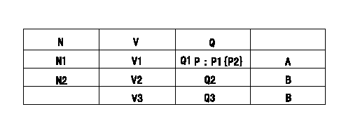
Adjusting method [applied voltage Vi, dummy bolt (C)]
1. Hold the dummy bolt (C) against the control lever at position N = N1, Q = Q1.
Fix using the lock nut.
2. When adjusting the potentiometer, position the control lever against the dummy bolt (C) and adjust the potentiometer so that the output voltage is V1 (V).
3. Remove the dummy bolt (C) after the completion of adjustment.
Confirm that the potentiometer output voltage is within the above mentioned standards between the control lever's adjusting point and the idling position.
N:Pump speed
V:Output voltage
Q:Injection quantity
P:Boost pressure
A:Adjusting point
B:Checking point
Q2:Idle
Q3:Full speed
----------
N1=700r/min V1=3.06+-0.03V Q1=33.3+-1cm3/1,000st Vi=10V
----------
N1=700r/min N2=425r/min V1=3.06+-0.03V V2=Measure V3=-V Q1=33.3+-1cm3/1,000st Q2=10.5+-2cm3/1,000st(Idle) Q3=-cm3/1,000st P1=-kPa P2=-mmHg
----------
N1=700r/min V1=3.06+-0.03V Q1=33.3+-1cm3/1,000st Vi=10V
----------
N1=700r/min N2=425r/min V1=3.06+-0.03V V2=Measure V3=-V Q1=33.3+-1cm3/1,000st Q2=10.5+-2cm3/1,000st(Idle) Q3=-cm3/1,000st P1=-kPa P2=-mmHg
0000001901 V-FICD ADJUSTMENT
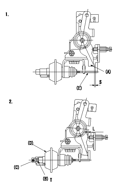
Adjustment of the V-FICD
1. Adjust to obtain S. Confirm full stroke when P1 {P2} negative pressure is applied.
2. Confirm that L is obtained when negative pressure P = P1 {P2} is applied to the actuator.
To adjust the stroke adjust the actuator's stroke adjusting screw (C).
(A) Control lever
(B) Locknut
(C) Stroke adjusting screw
(D) Actuator
(e) Actuator shaft
----------
S=1+1mm L=0.56+-0.2mm P1=-53.3kPa P2=-400mmHg
----------
S=1+1mm L=0.56+-0.2mm T=1.2~1.5N-m{0.12~0.15kgf-m}
----------
S=1+1mm L=0.56+-0.2mm P1=-53.3kPa P2=-400mmHg
----------
S=1+1mm L=0.56+-0.2mm T=1.2~1.5N-m{0.12~0.15kgf-m}
0000002001 A/T PLATE ADJUSTMENT
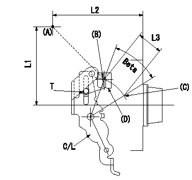
A/T plate adjustment
1. Turn the control lever from the idle position (B) to the Full speed position (C)
2. Adjust the A/T plate (D) so that (A)(C) - (A)(B) = L3, then fix.
----------
L3=33+-0.5mm
----------
L1=95.5mm L2=109.5mm L3=33+-0.5mm T=3.5~5N-m(0.35~0.5kgf-m)
----------
L3=33+-0.5mm
----------
L1=95.5mm L2=109.5mm L3=33+-0.5mm T=3.5~5N-m(0.35~0.5kgf-m)
0000002101 W-CSD ADJUSTMENT
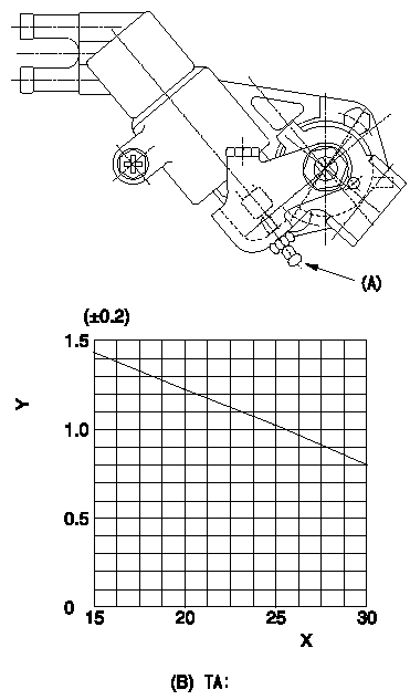
Adjustment of the W-CSD
Adjustment of the timer advance angle
1. Determine the timer advance angle using the graph.
2. Adjust with the screw (A) so that the timer advance angle determined in item 1 is obtained.
X:Temperature t (deg C)
Y:Timer stroke TA (mm)
(B): Timer stroke (mm)
----------
----------
TA=TA=-0.041t+2.05
----------
----------
TA=TA=-0.041t+2.05
Information:
Bearings
Anti-Friction Bearings
When an anti-friction bearing is removed, cover it to keep out dirt and abrasives. Wash the bearings in nonflammable cleaning solution and allow them to drain dry. The bearings may be dried with compressed air, but DO NOT SPIN THE BEARING. Discard the bearings if the races and balls or rollers are pitted, scored or burned. If the bearing is serviceable, coat it with oil and wrap it in clean paper. DO NOT unwrap new bearings until time of installation.The life of an anti-friction bearing will be shortened if not properly lubricated.Double Row, Tapered Roller
Double row, tapered roller bearings are precision fit during manufacture and the components are not interchangeable. The cups, cones and spacers are usually etched with the same serial number and letter designator. If no letter designators are found, wire the components together to assure correct installation. Reusable bearing components should be installed in their original positions.Heating Bearings
Bearings which require expansion for installation should be heated in oil not to exceed 121°C (250°F). When more than one part is heated to aid in assembly, they must be allowed to cool and then pressed together again. Parts often separate as they cool and shrink.Installation
Lubricate new or used bearings before installation. Bearings that are to be preloaded must have a film of oil over the entire assembly to obtain accurate preloading. When installing a bearing, spacer or washer against a shoulder on a shaft, be sure the chamfered side is toward the shoulder. When pressing bearings into a retainer or bore, apply pressure to the outer race. If the bearing is pressed on the shaft, apply pressure on the inner race.Preload
Preload is an initial force placed on the bearing at the time of assembly.Determine preload or end clearance form the Specifications Section of this Service Manual. Care should be exercised in applying preload. Misapplication of preload to bearings requiring end clearance can result in bearing failure.Sleeve Bearings
DO NOT INSTALL SLEEVE BEARINGS WITH A HAMMER. Use a press, if possible and apply the pressure directly in line with the bore. If it is necessary to drive on a bearing, use a driver or a bar with a smooth flat end. If a sleeve bearing has an oil hole, align it with the oil hole in the mating part.